APPENDIX C
STATIC ACCURACY
This appendix illustrates techniques that are available for determining the system accuracy. These are referred to several times in this book.
A method for determining the steady-state performance of any control system is to apply the final-value theorem of the Laplace transform. Let us consider the unity-feedback system shown in Figure C.1. The relation between the resulting system error, E(s), for a given input R(s) is given by
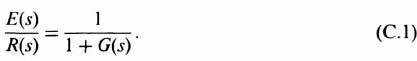
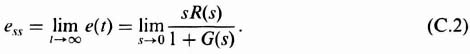
The steady-state error can be expressed as
The control engineer is usually interested in test inputs of position, velocity, and acceleration. A step, ramp, and paraboloid are simple mathematical expressions which represent these physical quantities, respectively, and is illustrated in Figure C.2. They are defined in Eqs. (C.3)–(C.5), where the notation U(t) means a unit step for t ![]() 0:
0:
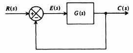
Figure C.1 A unity-feedback system.
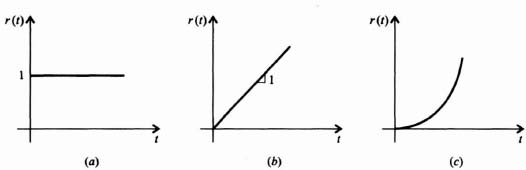
Figure C.2 Test inputs (a) Unit step representing a position input. (b) Unit ramp representing a velocity input. ...
Get Advanced Modern Control System Theory and Design now with the O’Reilly learning platform.
O’Reilly members experience books, live events, courses curated by job role, and more from O’Reilly and nearly 200 top publishers.

