
80 S. Norman and R. Bellamkonda
Figure 4.7. An ECoG electrode array located on top of the cortex but inside the skull.
91
Reprinted with permission from the Journal of Neural Engineering, Leuthanrdt et al., 2004,
Vol 1, Issue 2, pp 63–71. For color reference, see page 259.
and they are constantly being improved to increase accuracy and decrease the
amount of training time needed. It has been shown in monkeys with Utah arrays
implanted over the arm representation in the premotor cortex that predictive
models about arm movement speed up processing and could allow BCI users
to perform functions more quickly than theyareabletowithtraditionalBCI
algorithms.
91
Signal processing algorithms are dependent on the method of signal
acquisition to some degree; programs to process single neuron unit data will be-
have differently from programs to interpret EEG scalp recordings, which typically
consist of the summation of thousands of neurons near the cortical surface.
BCIs have a great deal of clinical promise, but they also need refinement before
they can be used in widespread clinical trials. Once developed and refined, BCIs
have the potential to allow paralyzed and locked-in patients to interact with the
world around them and improve their quality of life.
4.3 DEVICE CONCERNS AND TISSUE RESPONSE
As with any biological implant, the materials used for a MEMs neural interface
must be biologically compatible. The device should not leach toxic materials into
the organism and should not be detrimental to the health of the animal; it also
should not deteriorate over time, unless biodegradation is the goal. Most implant
materials, even if biocompatible, trigger an inflammatory response when left in the
body for extended periods of time, and the nervous system is no exception.
The initial insertion of microelectrodes into brain or spinal cord is likely to be
harsh on the tissue. It is speculated that when a probe is inserted, it tears cells
and the surrounding tissue, and this damage triggers a cascade of events that will
manifest themselves as the inflammatory response.
92
The inflammatory response
SO13997_text.indd 88SO13997_text.indd 88 26/01/2011 3:50 PM26/01/2011 3:50 PM
MEMS in the Nervous System 81
is divided into acute and chronic phases; during the acute phase, microglia become
activated and respond to the foreign electrode.
92
It is suspected that immune cells
circulating through the blood may also enter the brain,
93
possibly via breached
blood vessels. Microglia can be seen around an electrode as soon as 24 hours after
the implant.
93
The acute phase lasts for approximately 1–3 weeks after insertion,
after which the chronic phase begins.
92
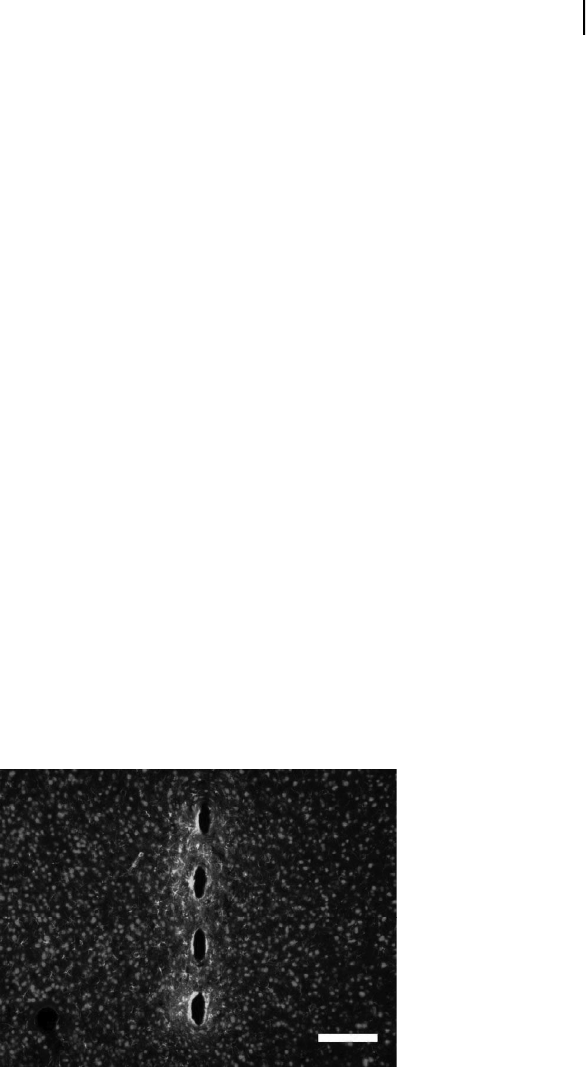
One of the attributes of the chronic phase of inflammation is an astrocytic
sheath formed around the implant (Fig. 4.8).
92
Resting astrocytes form the blood
brain barrier, buffer excess potassium and neurotransmitters, and may supply
neurons with nutrients.
94
When astrocytes become reactive, they can secrete com-
pounds inhibitory to neural growth, such as chondroitin sulfate proteoglycans
(CSPGs).
95,96
Thesheathformedaroundtheelectrodegrowsinsizeforabout
6 weeks and then becomes thinner and denser.
93
Microglia are located on the
inside of this astroglial sheath;
97
activated microglia have been shown to release
inflammatory cytokines and reactive oxygen species (see Block and Hong for
review
98
), and this constant release of compounds from activated microglia can
be neurotoxic.
99
It has been shown that a region devoid of neurons appears next to
an implanted electrode.
97
Thus, the neurons from which the probe is most likely
to record signals may be killed because of this chronic foreign body response. The
dense glial encapsulation may also interfere with electrical recording by forming
a high-impedance layer around the electrode,
100
so several strategies have been
employed to lessen the severity of the glial response. Groups have experimented
with modifying electrode cross section, geometry, and tip shape, but none of these
parameters appears to mitigate the chronic glial response.
93
Electrode coatings
have been developed to enhance neuronal attachment,
101
butitisnotclearifthis
Figure 4.8. The response of rat cortical tissue 8 weeks after insertion. The green stain
marks glial fibrillary acidic protein (GFAP), a marker for astrocytes, and the red NeuN stain
marks neuron nuclei. The scale bar is 100 micrometers. Notice the astrocytes apparent
at the electrode interface, and that the neurons appear further away. Image courtesy of
George McConnell, Bellamkonda Lab, Georgia Institute of Technology. For color reference,
see page 260.
SO13997_text.indd 89SO13997_text.indd 89 26/01/2011 3:50 PM26/01/2011 3:50 PM
Get Biomaterials for MEMS now with the O’Reilly learning platform.
O’Reilly members experience books, live events, courses curated by job role, and more from O’Reilly and nearly 200 top publishers.

