128 V. Bazargan and B. Stoeber
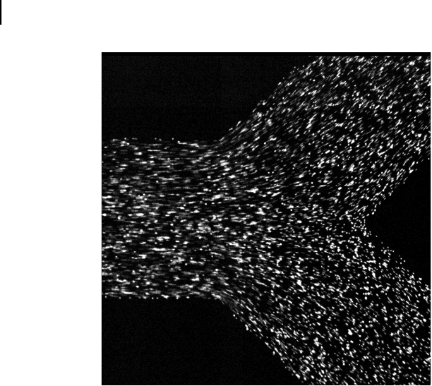
Figure 6.8. An image of the 0.7 μm large fluorescent seed particles in the microchannels
showninFig.6.6.
time between image frames. Valve closing and opening has been demonstrated
for 0.25 - 4 Hz cycles of 100 ms to 1 s long 400 mW pulses.
The time scale for thermal diffusion across the height of the channel limits
the dynamic response of this valve. Assuming the thermal diffusivity of water
α =1.41· 10
−7
m
2
/s as a good approximation for the thermal diffusivity of the
Pluronic solution, the thermal time scale t
d
∼ H
2
/α for heat diffusion across
a channel of height H =10μm is less than 1 ms as discussed in Section 6.2.
Optimizing the pulse shape of the heating voltage applied to the heaters should
yiels a valve responses below 1 ms.
6.5.2 Passive Valving
6.5.2.1 C oncept for Passive Flow Control
In addition to active flow control in microfluidic systems using Pluronic solutions,
their usefulness for passive flow control has been demonstrated as well.
26,53,72
The concept for active flow control discussed in the previous section relies on
a significant temperature change of the Pluronic solution that leads to a rapid
transition across the phase transition temperature, where rapid heating results in
rapid gel formation, and cooling leads to liquefaction.
A concept for passive flow control using Pluronic solutions uses a small
amount of heat generated in the fluid through viscous heating. Viscous heating
describes heat generated through internal friction in a fluid that is in motion,
SO13997_text.indd 136SO13997_text.indd 136 26/01/2011 3:50 PM26/01/2011 3:50 PM
Flow Control in Biomedical Microdevices using Thermally Responsive Fluids 129
D
E
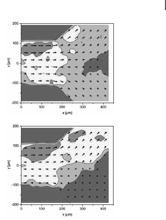
Figure 6.9. The flow field at the channel bifurcation shown in Fig. 6.6. The velocities
were evaluated from images of the seed particles as in Fig. 6.8 using PIV; (a) before valve
actuation, (b) 33 ms later; blue: below 40 μm/s, green: 40–80 μm/s, yellow: 80–120 μm/s,
orange: 120–160 μm/s. For color reference, see page 267.
where neighboring fluid layers in shear flow move at different speeds. The rate
of viscous heating Φ can be approximated by μ (
˙
γ)
2
with the shear rate
˙
γ=∂U/∂y
indicating the change in velocity perpendicular to the flow direction. This means
that at high shear rates, heat will be produced the fluid temperature will increase.
If the Pluronic solution is already near the phase boundary, only a small increase in
temperature is required for a transition from the liquid phase to the soft gel phase.
6.5.2.2 Demonstration of Passive Valving
A straight microchannel with a rectangular cross section was fabricated through
deep reactive ion etching (DRIE) of a trench into silicon followed by anodic
bonding of a Pyrex lid to the silicon substrate. The device was connected to a
SO13997_text.indd 137SO13997_text.indd 137 26/01/2011 3:50 PM26/01/2011 3:50 PM
130 V. Bazargan and B. Stoeber
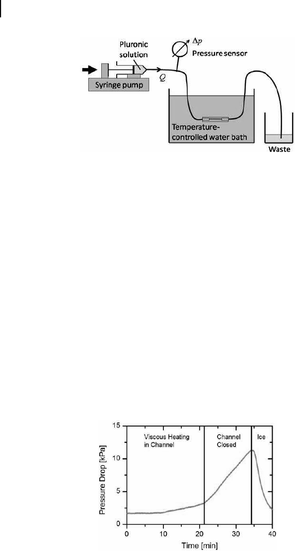
Figure 6.10. Experimental setup for the demonstration of passive flow control using
thermally responsive Pluronic solutions at constant flow rate in microchannels. For color
reference, see page 268.
syringe pump with flexible polymer tubing, and a gauge pressure sensor was
attached between the syringe pump and the microchannel as shown in Fig. 6.10.
The fluid drained from the channel through a piece of tubing to atmosphere.
The gauge pressure recorded therefore corresponded to the pressure along the
microchannel, neglecting the pressure drop along the wide flexible tubing on either
end of the microchannel. The microchannel was submerged in a temperature-
controlled water bath to achieve well-defined temperature conditions.
A 13 wt% Pluronic F127 solution was pumped through the microchannel at
aflowrateQ =0.5μL/min using a syringe pump. The device temperature was
maintained at 27
◦
C with the temperature-controlled water bath, which is well
below the gel formation temperature of 31
◦
C of the Pluronic solution. After
initiating the flow, the pressure along the channel reached a constant value as
shown in Fig. 6.11. The pressure then increased, first slowly, and then more rapidly
at a nearly constant rate. After holding ice against the device, the pressure rapidly
decreased.
Figure 6.11. Pressure recorded along a 10 mm long microchannel with rectangular cross
section (150 μm × 100 μm) for a 13 wt% Pluronic F127 solution at 27
◦
Cdriventhroughthe
channel at a flow rate 0.5 μL/min. At around 34 minutes, ice was held against the device to
lower its temperature.
SO13997_text.indd 138SO13997_text.indd 138 26/01/2011 3:50 PM26/01/2011 3:50 PM
Get Biomaterials for MEMS now with the O’Reilly learning platform.
O’Reilly members experience books, live events, courses curated by job role, and more from O’Reilly and nearly 200 top publishers.

