Chapter 2
Self-controlled Synchronous Motor: Dynamic Model Including the Behavior of Damper Windings and Commutation Overlap 1
2.1. Introduction
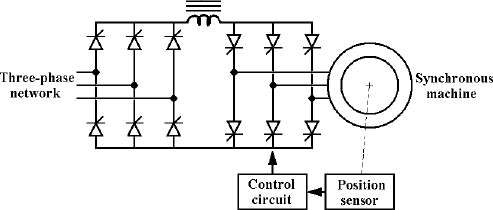
This chapter studies the same system examined in Chapter 1 – a synchronous motor supplied by a thyristor bridge operating as a current inverter and a control system that links the starting angle of the thyristors to the rotor position, as can be seen in Figure 2.1.
Figure 2.1. Principle diagram of the self-controlled synchronous machine (identical to the diagram in Figure 1.1)

The aim is to develop a macroscopic model similar to that presented in section 1.10. This will take into account the transient regime due to the damper windings, without making the hypothesis that the overlap angle (the electric angle during which the armature current is transferred from one phase to the other during the commutation) is zero. As in Chapter 1, we will assume that the synchronous machine has a cylindrical rotor, the couplings between the windings are sinusoidal, the field winding is supplied with a current source and that there is no magnetic saturation.
Since the overlap angle is not assumed to be zero, the model obtained will have at least one more degree of freedom, and thus need an additional equation to set this. It will have to remain simple enough to be used in a control system. To define the armature circuit, we will use a variable that, ...
Get Control of Non-conventional Synchronous Motors now with the O’Reilly learning platform.
O’Reilly members experience books, live events, courses curated by job role, and more from O’Reilly and nearly 200 top publishers.

