1.8 Mutual and Self-Capacitance
In a typical capacitor, the electric field lines start on one conductor and terminate on the second conductor. The conductor at zero volts is often called the reference conductor. The ratio of charge on the first conductor to the charge on that of the second conductor is called self-capacitance. The capacitors used in a circuit all have self-capacitances.
When there is a group of conductors as in a circuit, the concept of capacitance must be extended to allow for cross coupling. As an example, consider traces over a ground plane as in Figure 1.2. The ground plane can be considered the reference conductor at zero volts.
Figure 1.2 Mutual capacitance between traces on a circuit board.
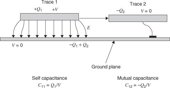
Assume that one of the traces is at a voltage V1 and all the other conductors are at zero volts. By definition the self-capacitance C11 of trace 1 is the ratio of charge on trace 1 to the voltage on trace 1 or Q1/V1. When trace 1 is at potential V1, some of the electric field lines terminate on trace 2. This represents an induced charge Q2 on this conductor. The ratio of Q2/V1 = C21 is called a mutual capacitance. Since the field lines always terminate on charges of opposite polarity this ratio is always negative.
Mutual capacitance can allow an induced current to flow in nearby circuits. ...
Get Digital Circuit Boards: Mach 1 GHz now with the O’Reilly learning platform.
O’Reilly members experience books, live events, courses curated by job role, and more from O’Reilly and nearly 200 top publishers.

