2.11 Discharging a Charged Open Transmission Line
Figure 2.9 shows a length of transmission line that has a characteristic impedance Z of 5 ohm. In this example, the line is initially charged to a voltage of 5 V.
Figure 2.9 The voltage waveform when a transmission line is discharged.
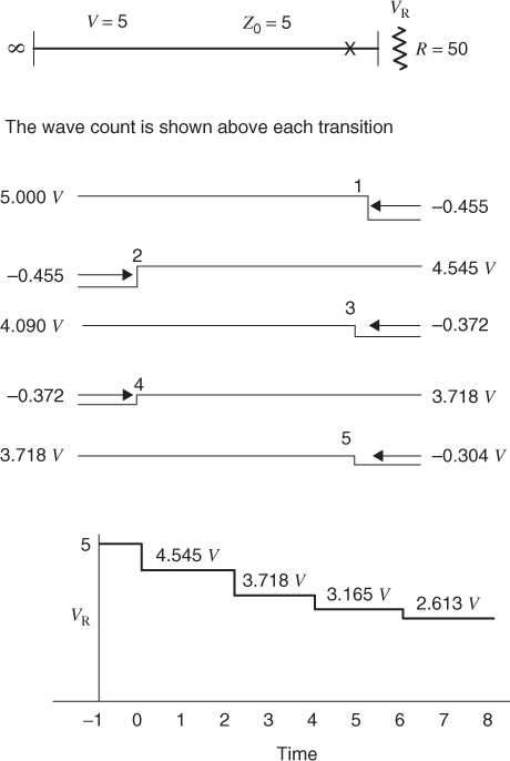
At time t = 0, a switch closes and the line is terminated in a resistor R of 50 ohm. At this moment, a step voltage of 4.54 V appears at the load. A step wave (1) of −0.46 V propagates back into the line. At the open end of the line, wave (1) is reflected. The resulting return voltage is 4.08 V. When wave (2) reaches the load, some of the wave energy is transmitted into the load and some is reflected. In this example, the load voltage drops to 3.71 V. After the next round trip of wave motion, the load voltage drops to 3.06 V. The reflection process continues with waves traveling back and forth between the load and the open end of the transmission line. Each time a wave makes a round trip, the energy flowing into the load from the transmission line is reduced. The envelope of decreasing voltage follows an exponential curve with the voltage reduced by the same factor after each round trip. In this example, wave fronts with very short rise and fall times are shown so that the reflection process is clear.
The section of transmission line in Figure 2.9 could represent a capacitor. In circuit theory, the ...
Get Digital Circuit Boards: Mach 1 GHz now with the O’Reilly learning platform.
O’Reilly members experience books, live events, courses curated by job role, and more from O’Reilly and nearly 200 top publishers.

