2.15 The Energy Flow Through Cascaded (Series) Transmission Lines
Consider two transmission lines in series as in Figure 2.11. Line 1 has a length d1, characteristic impedance Z1, and dielectric constant ε 1. Line 2 has values d2, Z2, and ε 2. Initially, the entire line is charged to voltage V. We are interested in the way the voltage builds up in the load R after the switch closes. There are two cases to consider.
Figure 2.11 Taking energy from the ground/power plane.
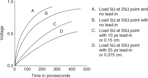
Case 1. Line 2 is a short section of high impedance line where Z1 Z2. As a practical example, consider that line 1 is 10 cm long and has a characteristic impedance of 0.5 ohm and line 2 is 1.0 cm long and has a characteristic impedance of 50 ohm. Assume that the load resistor R is 5 ohm.
When the switch closes, the voltage at the load drops to approximately VR/Z2. This is also the amplitude of the negative wave that travels back to Z1. At the interface between the two lines, the initial wave reflects and reverses polarity. When this reflected wave returns to the load, it begins to bring energy to the load. Another way to see this is that the return wave adds an increment of voltage to the load. This wave reflects at the load and starts a wave that makes a second round trip. After each round trip, the voltage at the load rises by an increment. The result of these round trips is a growth in voltage that approaches ...
Get Digital Circuit Boards: Mach 1 GHz now with the O’Reilly learning platform.
O’Reilly members experience books, live events, courses curated by job role, and more from O’Reilly and nearly 200 top publishers.

