2.18 Parallel (Shunt) Terminations
In high speed circuits, parallel transmission line terminations can be useful. This termination is placed at the end of the transmission line as shown in Figure 2.15.
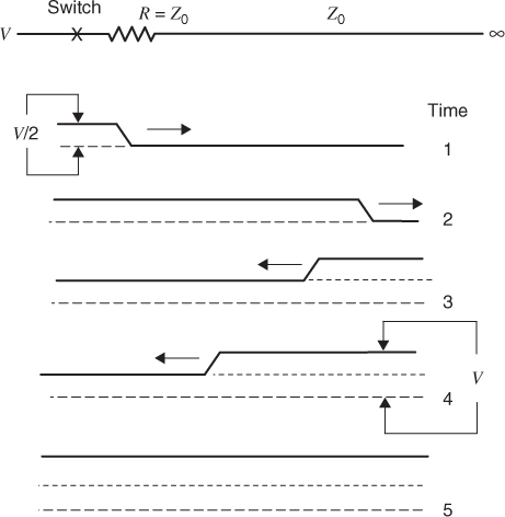
Figure 2.15 A series (source) terminated transmission line.
Since there is no reflection at the ends of the lines, line current continues to flow as long as there is a signal. Because of the extra power consumption, this technique is usually limited to low voltage logic. In general, this logic design approach has a higher noise margin than the series termination case.
In series terminated circuits, the clock signals are usually timed so that logic signals have time to reflect and return to the source. This timing guarantees that all logic connections made along the transmission path will receive the doubled voltage before the clock signal arrives.
On long lines with all the loads at the end of the lines, parallel terminations can be effective. The clock signal can arrive anytime after the logic signal reaches the termination. On a long line, compensation for line loss can be made by increasing the value of the terminating resistor. The reflection that results adds to the signal, thus, reducing the chances of error. Parallel termination has the drawback that energy must be supplied to the line as long as the logic signals are present. If the transmissions are infrequent and the logic ...
Get Digital Circuit Boards: Mach 1 GHz now with the O’Reilly learning platform.
O’Reilly members experience books, live events, courses curated by job role, and more from O’Reilly and nearly 200 top publishers.

