8Passband Modulation Techniques
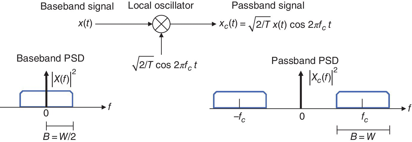
In baseband pulse transmission, a data stream, represented as a sequence of a discrete PAM signals, is transmitted directly over a low‐pass channel. However, in digital passband transmission, the input data stream is modulated onto a carrier, which occupies a transmission bandwidth in proportion with the data rate. This is achieved by multiplying the baseband signal x(t) with a carrier of frequency fc, generated by a local oscillator at the transmitter. The spectrum of the signal thus obtained is shifted to around fc as shown in Figure 8.1. The energy of the carrier signal generated by the local oscillator is assumed to be unity so that the energy of the baseband signal is not changed with frequency conversion. However, the bandwidth of the passband signal becomes twice as large as that of the baseband signal (see Figure 8.1).

Figure 8.1 Passband Signal. X(f) denotes the Fourier transform of the baseband signal x(t).
The signal bandwidth, that is, the bandwidth occupied by the signal, should be narrower than the channel bandwidth, that is, the bandwidth allowed by the transmission channel. Otherwise, intersymbol interference (ISI) and some other distortions may arise in the signal at the receiver input. In this context, one is faced with the dilemma between the requirements for higher data rates and lower transmission bandwidths. The transmission ...
Get Digital Communications now with the O’Reilly learning platform.
O’Reilly members experience books, live events, courses curated by job role, and more from O’Reilly and nearly 200 top publishers.

