Chapter 2. Getting Started
The Arduino board provides easy access to the digital and analog input and output pins of the microcontroller so that you can connect sensors and actuators to the processor.[2] However, it’s not always possible to use those pins directly. Most sensors will need some additional supporting circuitry, and there are never enough power and ground pins to go around. What we need is some way to design and lay out our circuit—and perhaps more crucially, change our minds as we go along. The easiest way to do that is to use something called a breadboard.
The Breadboard
A solderless breadboard is an indispensable tool for rapidly and cheaply prototyping projects.
Breadboards consist of many tiny “holes” arranged on a 0.1-inch grid into which the leads of the component can be connected. Typically, as in Figure 2-1, the holes down each side of the breadboard are electrically connected lengthways down the board and are used for the positive and negative (i.e., ground or Earth) power supply. These are usually referred to as rails, and will commonly be labeled as such. The other holes in the board are connected horizontally across the board, usually (and again, as in Figure 2-1) with a gap down the middle. Each hole is connected to the many metal strips that are running underneath the board.
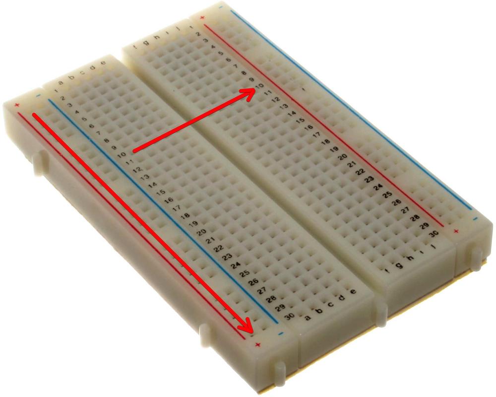
Figure 2-1. A typical mini breadboard
Putting the legs of a component in the same row, ...
Get Distributed Network Data now with the O’Reilly learning platform.
O’Reilly members experience books, live events, courses curated by job role, and more from O’Reilly and nearly 200 top publishers.

