Chapter 12. Cams
Chapter Objectives
• Learn how to draw cams using SolidWorks
• Learn how to draw displacement diagrams
• Understand the relationship between cams and followers
12-1 Introduction
Cams are mechanical devices used to translate rotary motion into linear motion. Traditionally, cam profiles are designed by first defining a displacement diagram and then transferring the displacement diagram information to a base circle. Figure 12-1 shows a cam and a displacement diagram.
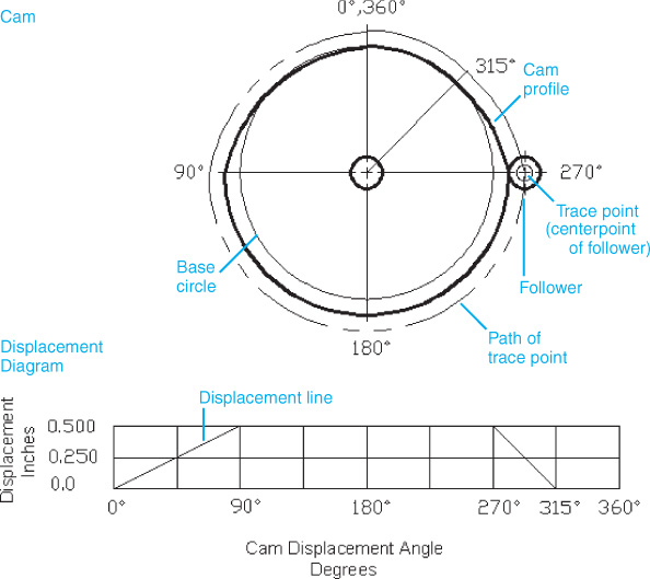
Figure 12-1
12-2 Base Circle
Cam profiles are defined starting with a base circle. The diameter of the base circle will vary according to the design situation. ...
Get Engineering Design and Graphics with SolidWorks® 2014 now with the O’Reilly learning platform.
O’Reilly members experience books, live events, courses curated by job role, and more from O’Reilly and nearly 200 top publishers.

