Ethernet is by far the most widely used local area networking (LAN) technology in the world today. Market surveys indicate that hundreds of millions of Ethernet network interface cards (NICs), repeater ports, and switching hub ports have been sold to date, and the market continues to grow. In total, Ethernet outsells all other LAN technologies by a very large margin.
Ethernet reached its 25th birthday in 1998, and has seen many changes as computer technology evolved over the years. Ethernet has been constantly reinvented, evolving new capabilities and in the process growing to become the most popular network technology in the world.
This chapter describes the invention of Ethernet, and the development and organization of the Ethernet standard. Along the way we provide a brief tour of the entire set of Ethernet media systems.
On May 22, 1973, Bob Metcalfe (then at the Xerox Palo Alto Research Center, PARC, in California) wrote a memo describing the Ethernet network system he had invented for interconnecting advanced computer workstations, making it possible to send data to one another and to high-speed laser printers. Probably the best-known invention at Xerox PARC was the first personal computer workstation with graphical user interfaces and mouse pointing device, called the Xerox Alto. The PARC inventions also included the first laser printers for personal computers, and, with the creation of Ethernet, the first high-speed LAN technology to link everything together.
This was a remarkable computing environment for the time, since the early 1970s were an era in which computing was dominated by large and very expensive mainframe computers. Few places could afford to buy and support mainframes, and few people knew how to use them. The inventions at Xerox PARC helped bring about a revolutionary change in the world of computing.
A major part of this revolutionary change in the use of computers has been the use of Ethernet LANs to enable communication among computers. Combined with an explosive increase in the use of information sharing applications such as the World Wide Web, this new model of computing has brought an entire new world of communications technology into existence. These days, sharing information is most often done over an Ethernet; from the smallest office to the largest corporation, from the single schoolroom to the largest university campus, Ethernet is clearly the networking technology of choice.
Bob Metcalfe’s 1973 Ethernet memo describes a networking system based on an earlier experiment in networking called the Aloha network. The Aloha network began at the University of Hawaii in the late 1960s when Norman Abramson and his colleagues developed a radio network for communication among the Hawaiian Islands. This system was an early experiment in the development of mechanisms for sharing a common communications channel—in this case, a common radio channel.
The Aloha protocol was very simple: an Aloha station could send whenever it liked, and then waited for an acknowledgment. If an acknowledgment wasn’t received within a short amount of time, the station assumed that another station had also transmitted simultaneously, causing a collision in which the combined transmissions were garbled so that the receiving station did not hear them and did not return an acknowledgment. Upon detecting a collision, both transmitting stations would choose a random backoff time and then retransmit their packets with a good probability of success. However, as traffic increased on the Aloha channel, the collision rate would rapidly increase as well.
Abramson calculated that this system, known as pure Aloha, could achieve a maximum channel utilization of about 18 percent due to the rapidly increasing rate of collisions under increasing load. Another system, called slotted Aloha, was developed that assigned transmission slots and used a master clock to synchronize transmissions, which increased the maximum utilization of the channel to about 37 percent. In 1995, Abramson received the IEEE’s Koji Kobayashi Computers and Communications Award “for development of the concept of the Aloha System, which led to modern local area networks.”
Metcalfe realized that he could improve on the Aloha system of arbitrating access to a shared communications channel. He developed a new system that included a mechanism that detected when a collision occurred (collision detect). The system also included “listen before talk,” in which stations listened for activity (carrier sense) before transmitting, and supported access to a shared channel by multiple stations (multiple access). Put all these components together, and you can see why the Ethernet channel access protocol is called Carrier Sense Multiple Access with Collision Detect (CSMA/CD). Metcalfe also developed a more sophisticated backoff algorithm, which, in combination with the CSMA/CD protocol, allowed the Ethernet system to function at up to 100 percent load.
In late 1972, Metcalfe and his Xerox PARC colleagues developed the first experimental Ethernet system to interconnect the Xerox Alto. The experimental Ethernet was used to link Altos to one another, and to servers and laser printers. The signal clock for the experimental Ethernet interface was derived from the Alto’s system clock, which resulted in a data transmission rate on the experimental Ethernet of 2.94 Mbps.
Metcalfe’s first experimental network was called the Alto Aloha Network. In 1973, Metcalfe changed the name to "Ethernet,” to make it clear that the system could support any computer—not just Altos—and to point out that his new network mechanisms had evolved well beyond the Aloha system. He chose to base the name on the word “ether” as a way of describing an essential feature of the system: the physical medium (i.e., a cable) carries bits to all stations, much the same way that the old " luminiferous ether” was once thought to propagate electromagnetic waves through space.[1] Thus, Ethernet was born.
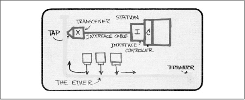
In 1976, Metcalfe drew the following diagram (Figure 1.1) “...to present Ethernet for the first time. It was used in his presentation to the National Computer Conference in June of that year. On the drawing are the original terms for describing Ethernet. Since then, other terms have come into usage among Ethernet enthusiasts.”[2]
In July 1976, Bob Metcalfe and David Boggs published their landmark paper “Ethernet: Distributed Packet Switching for Local Computer Networks,” in the Communications of the Association for Computing Machinery (CACM). In late 1977, Robert M. Metcalfe, David R. Boggs, Charles P. Thacker, and Butler W. Lampson received U.S. patent number 4,063,220 on Ethernet for a “Multipoint Data Communication System With Collision Detection.” A patent for the Ethernet repeater was issued in mid-1978. At this point, Xerox wholly owned the Ethernet system. The next stage in the evolution of the world’s most popular computer network was to liberate Ethernet from the confines of a single corporation and make it a worldwide standard.
The original 10 Mbps Ethernet standard was first published in 1980 by the DEC-Intel-Xerox vendor consortium. Using the first initial of each company, this became known as the DIX Ethernet standard. This standard, entitled The Ethernet, A Local Area Network: Data Link Layer and Physical Layer Specifications, contained the specifications for the operation of Ethernet as well as the specs for a single media system based on thick coaxial cable. As is true for most standards, the DIX standard was revised to add some technical changes, corrections, and minor improvements. The last revision of this standard was DIX V2.0.
When the DIX standard was published, a new effort led by the Institute of Electrical and Electronics Engineers (IEEE) to develop open network standards was also getting underway.[3] Consequently, the thick coaxial variety of Ethernet ended up being standardized twice—first by the DIX consortium and a second time by the IEEE. The IEEE standard was created under the direction of the IEEE Local and Metropolitan Networks (LAN/MAN) Standards Committee, which identifies all the standards it develops with the number 802. There have been a number of networking standards published in the 802 branch of the IEEE, including the 802.3[4] Ethernet and 802.5 Token Ring standards.
The IEEE 802.3 committee took up the network system described in the original DIX standard and used it as the basis for an IEEE standard. The IEEE standard was first published in 1985 with the title IEEE 802.3 Carrier Sense Multiple Access with Collision Detection (CSMA/CD) Access Method and Physical Layer Specifications . The IEEE standard does not use “Ethernet” in the title, even though Xerox relinquished their trademark on the Ethernet name. That’s because open standards committees are quite sensitive about using commercial names that might imply endorsement of a particular company. As a result, the IEEE calls this technology 802.3 CSMA/CD or just 802.3. However, most people still use the Ethernet name when referring to the network system described in the 802.3 standard.
The IEEE 802.3 standard is the official Ethernet standard. From time to time you may hear of other Ethernet technology “standards” developed by various groups or vendor consortiums. However, if the technology isn’t specified within the IEEE 802.3 standard, it isn’t an official Ethernet technology. Periodically, the latest IEEE 802.3 standards are presented to the American National Standards Institute (ANSI), which forwards them on, where they are adopted by the International Organization for Standardization (ISO). This organization is described in more detail later in this chapter. Adoption by the ISO means that the IEEE 802.3 Ethernet standard is also a worldwide standard, and that vendors from around the globe can build equipment that will work together on Ethernet systems.
After the publication of the original IEEE 802.3 standard for thick Ethernet, the next development in Ethernet media was the thin coaxial Ethernet variety, inspired by technology first marketed by the 3Com Corporation. When the IEEE 802.3 committee standardized the thin Ethernet technology, they gave it the shorthand identifier of 10BASE2, which is explained later in this chapter.
Following the development of thin coaxial Ethernet came several new media varieties, including the twisted-pair and fiber optic varieties for the 10 Mbps system. Next, the 100 Mbps Fast Ethernet system was developed, which also included several varieties of twisted-pair and fiber optic media systems. Most recently, the Gigabit Ethernet system was developed using both fiber optic and twisted-pair cabling. These systems were all developed as supplements to the IEEE Ethernet standard.
When the Ethernet standard needs to be changed to add a new media system or capability, the IEEE issues a supplement which contains one or more sections, or “clauses” in IEEE-speak. The supplement may consist of one or more entirely new clauses, and may also contain changes to existing clauses in the standard. New supplements to the standard are evaluated by the engineering experts at various IEEE meetings and the supplements must pass a balloting procedure before being voted into the full standard.
New supplements are given a letter designation when they are created. Once the supplement has completed the standardization process, it becomes part of the base standard and is no longer published as a separate supplementary document. On the other hand, you will sometimes see trade literature that refers to Ethernet equipment with the letter of the supplement in which the variety was first developed (e.g., IEEE 802.3u may be used as a reference for Fast Ethernet). Table 1.1 lists several supplements and what they refer to. The dates indicate when formal acceptance of the supplement into the standard occurred. Access to the complete set of supplements is provided in Appendix A.
Table 1.1. IEEE 802.3 Supplements
|
Supplement |
Description |
|---|---|
|
802.3a-1985 |
10BASE2 thin Ethernet |
|
802.3c-1985 |
10 Mbps repeater specifications, clause 9 |
|
802.3d-1987 |
FOIRL fiber link |
|
802.3i-1990 |
10BASE-T twisted-pair |
|
802.3j-1993 |
10BASE-F fiber optic |
|
802.3u-1995 |
100BASE-T Fast Ethernet and Auto-Negotiation |
|
802.3x-1997 |
Full-Duplex standard |
|
802.3z-1998 |
1000BASE-X Gigabit Ethernet |
|
802.3ab-1999 |
1000BASE-T Gigabit Ethernet over twisted-pair |
|
802.3ac-1998 |
Frame size extension to 1522 bytes for VLAN tag |
|
802.3ad-2000 |
Link aggregation for parallel links |
If you’ve been using Ethernet for a while, you may recall times when a new variety of Ethernet equipment was being sold before the supplement that described the new variety had been entirely completed or voted on. This illustrates a common problem: innovation in the computer field, and especially in computer networking, always outpaces the more deliberate and slow-paced process of developing and publishing standards. Vendors are eager to develop and market new products, and it’s up to you, the customer, to make sure that the product will work properly in your network system. One way you can do that is to insist on complete information from the vendor as to what standard the product complies with.
It may not be a bad thing if the product is built to a draft version of a new supplement. Draft versions of the supplements can be substantially complete yet still take months to be voted on by the various IEEE committees. When buying pre-standard equipment built to a draft of the specification, you need to ensure that the draft in question is sufficiently well along in the standards process that no major changes will be made. Otherwise, you could be left out in the cold with network equipment that won’t interoperate with newer devices that are built according to the final published standard. One solution to this is to get a written guarantee from the vendor that the equipment you purchase will be upgraded to meet the final published form of the standard. Note that the IEEE forbids vendors to claim or advertise that a product is compliant with an unapproved draft.
When the IEEE adopted the original DIX standard it made a few changes in the specifications. The major reason for the changes made between the DIX and IEEE standards is that the two groups had different goals. The specifications for the original DIX Ethernet standard were developed by the three companies involved and were intended to describe the Ethernet system—and only the Ethernet system. At the time the multi-vendor DIX consortium was developing the first Ethernet standard, there was no open LAN market, nor was there any other multi-vendor LAN standard in existence. The efforts aimed at creating a worldwide system of open standards had only just begun.
On the other hand, the IEEE was developing standards for integration into the world of international LAN standards. Consequently, the IEEE made several technical changes required for inclusion in the worldwide standardization effort. The IEEE specifications permit backward compatibility with early Ethernet systems built according to the original DIX specifications.[5] The goal is to standardize network technologies under one umbrella, coordinated with the International Organization for Standardization.
The IEEE standards are organized according to the Open Systems Interconnection (OSI) Reference Model. This model was developed in 1978 by the International Organization for Standardization, whose initials (derived from its French name) are ISO. Headquartered in Geneva, Switzerland, the ISO is responsible for setting open, vendor-neutral standards and specifications for items of technical importance. For example, if you’re a photographer you’ve no doubt noticed the ISO standard speeds for camera film.
The ISO developed the OSI reference model to provide a common organizational scheme for network standardization efforts (with perhaps an additional goal of keeping us all confused with reversible acronyms). What follows is a quick, and necessarily incomplete, introduction to the subject of network models and international standardization efforts.
The OSI reference model is a method of describing how the interlocking sets of networking hardware and software can be organized to work together in the networking world. In effect, the OSI model provides a way to arbitrarily divide the task of networking into separate chunks, which are then subjected to the formal process of standardization.
To do this, the OSI reference model describes seven layers of networking functions, as illustrated in Figure 1.2. The lower layers cover the standards that describe how a LAN system moves bits around. The higher layers deal with more abstract notions, such as the reliability of data transmission and how data is represented to the user. The layers of interest for Ethernet are the lower two layers of the OSI model.
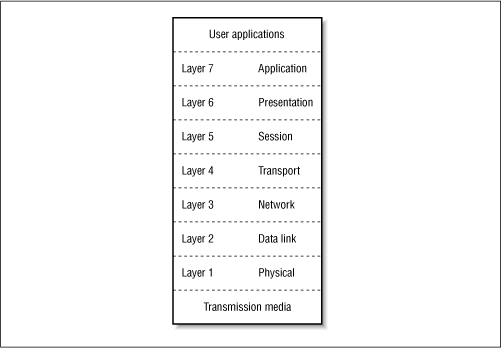
In brief, the OSI reference model includes the following seven layers, starting at the bottom and working our way to the topmost layer:
- Physical layer
Standardizes the electrical, mechanical, and functional control of data circuits that connect to physical media.
- Data link layer
Establishes communication from station to station across a single link. This is the layer that transmits and receives frames, recognizes link addresses, etc. The part of the standard that describes the Ethernet frame format and MAC protocol belongs to this layer.
- Network layer
Establishes communication from station to station across an internetwork, which is composed of a number of data links. This layer provides a level of independence from the lower two layers by establishing higher level functions and procedures for exchanging data between computers across multiple links. Standards at this layer of the model describe portions of the high-level network protocols that are carried over an Ethernet in the data field of the Ethernet frame. Protocols at this layer of the OSI model and above are independent of the Ethernet standard.
- Transport layer
Provides reliable end-to-end error recovery mechanisms and flow control in the higher level networking software.
- Session layer
Provides mechanisms for establishing reliable communications between cooperating applications.
- Presentation layer
Provides mechanisms for dealing with data representation in applications.
- Application layer
Provides mechanisms to support end-user applications such as mail, file transfer, etc.
The Ethernet standard concerns itself with elements described in Layer 2 and Layer 1, which include the data link layer of the OSI model and below. For that reason, you’ll sometimes hear Ethernet referred to as a link layer standard .
The Ethernet standards describe a number of entities that all fit within the data link and physical layers of the OSI model. To help organize the details, the IEEE defines extra sublayers that fit into the lower two layers of the OSI model, which simply means that the IEEE standard includes some more finely grained layering than the OSI model.
While at first glance these extra layers might seem to be outside the OSI reference model, the OSI model is not meant to rigidly dictate the structure of network standards. Instead, the OSI model is an organizational and explanatory tool; sublayers can be added to deal with the complexity of a given standard.
Figure 1.3 depicts the lower two layers of the OSI reference model, and shows how the major IEEE-specific sublayers are organized. Within these major sublayers there are even further sublayers defined for additional MAC functions, new physical signaling standards, and so on. At the data link level, there are the Logical Link Control (LLC) and the MAC sublayers, which are the same for all varieties and speeds of Ethernet. The LLC layer is an IEEE mechanism for identifying the data carried in an Ethernet frame. The MAC layer defines the protocol used to arbitrate access to the Ethernet system. Both of these systems are described in detail in Chapter 3 .
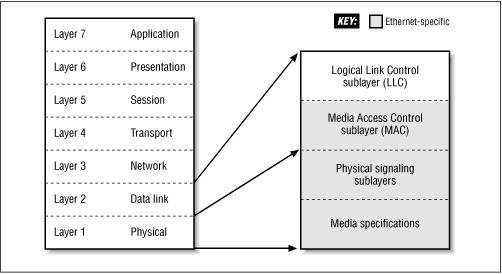
At the physical layer, the IEEE sublayers vary depending on whether 10-, 100-, or 1000 Mbps Ethernet is being standardized. Each of the sublayers is used to help organize the Ethernet specifications around specific functions that must be achieved to make the Ethernet system work.
Understanding these sublayers can also help us understand the scope of the various standards involved. For example, the MAC portion of the IEEE standard is “above” the lower layer physical specifications. As such, it is functionally independent of the various physical layer media specifications and does not change, no matter which physical media variety may be in use.
The IEEE LLC standard is independent of the 802.3 Ethernet LAN standard and will not vary—no matter which LAN system is used. The LLC control fields are intended for use in all LAN systems and not just Ethernet, which is why the LLC sublayer is not formally part of the IEEE 802.3 system specifications.
All of the sublayers below the LLC sublayer are specific to the individual LAN technology in question, which in this case is Ethernet. To help make this clearer, the Ethernet-specific portions of the standard in Figure 1.3 are all shown in gray.
Below the MAC sublayer, we get into the portions of the standard that are organized in the Physical Layer of the OSI reference model. The physical layer standards are different depending on the Ethernet media variety in use and whether or not we’re describing the original 10 Mbps Ethernet system, 100 Mbps Fast Ethernet, or 1000 Mbps Gigabit Ethernet system.
In developing a technical standard, the IEEE is careful to include only those items whose behavior must be carefully specified to make the system work. Therefore, all Ethernet interfaces that operate in the original half-duplex mode (described in Chapter 3) must comply fully with the MAC protocol specifications in the standard to perform the functions identically. Otherwise, the network would not function correctly.
At the same time, the IEEE makes an effort not to constrain the market by standardizing such things as the appearance of an Ethernet interface, or how many connectors it should have on it. The intent is to provide just enough engineering specifications to make the system work reliably, without inhibiting competition and the inventiveness of the marketplace. In general, the IEEE has been quite successful. Most equipment designed for use in an Ethernet system fully complies with the standard.
Vendor innovation can sometimes lead to the development of devices that are not described in the IEEE standard, and that are not included in the half-duplex mode timing specs or the media specs in the standard. Some of these devices may work well for a small network, but might cause problems with signal timing in a larger network operating in half-duplex mode. Further, a network system using equipment not described in the standard or included in the official guidelines cannot be evaluated using the IEEE half-duplex mode configuration guidelines.
How much you should be concerned about all this is largely up to you and your particular circumstances. Another way of saying this is: “Optimality differs according to context.”[6] It’s up to you to decide how important these issues are, given your particular circumstances (or context). For one thing, not all innovations are a bad idea.
After all, the thin coaxial and twisted-pair Ethernet media systems started life as vendor innovations that later became carefully specified media systems in the IEEE standard. However, if your goal is maximum predictability and stability for your network given a variety of vendor equipment and traffic loads, then one way to help achieve that goal is by using only equipment that is described in the standard.
One way to decide how important these issues are is to look at the scope and type of network system in question. For an Ethernet that just connects a couple of computers in your house, you may feel that any equipment you can find that helps make this happen at the least cost is a good deal. If the equipment isn’t described in the official half-duplex configuration guidelines, you may not care all that much. In this instance, you are building a small network system, and you probably don’t intend for the network to grow very large. The limited scope of your network makes it easier to decide that you are not all that worried about multi-vendor interoperability, or about your ability to evaluate the network using the IEEE configuration guidelines.
On the other hand, if you are a network manager of a departmental or campus network system, then the people using your network will be depending on the network to get their work done. The expanded scope changes your context quite a bit. Departmental and workgroup nets always seem to be growing, which makes extending networks to accommodate growth a major priority for you. In addition, network stability under all sorts of traffic loads becomes another important issue. In this very different context, the issues of multi-vendor interoperability and compliance with the standard become much more important.
All Ethernet equipment sold is compliant in some way with the standard; otherwise, it wouldn’t be able to interoperate with other Ethernet equipment. Therefore, mere compliance with the standard doesn’t tell you much. Unfortunately, there’s no LAN industry organization that will certify and stamp equipment, “This device is described in the standard and included in the official IEEE configuration guidelines.” That’s why you need to be wary about believing everything you read in equipment catalogs.
Sometimes vendors may not tell you whether the component they are selling is included in the IEEE system configuration guidelines, and whether it is a piece of standard and interoperable equipment that is widely available from other vendors. Some components that are not included in the official standard or media system configuration guidelines include the 10 Mbps AUI port concentrator, media converters, and special media segments. These components are described in later chapters and Appendix C.
The IEEE has assigned shorthand identifiers to the various Ethernet media systems as they have been developed. The three-part identifiers include the speed, the type of signaling used, and information about the physical medium.
In the early media systems, the physical medium part of the identifier was based on the cable distance in meters, rounded to the nearest 100 meters. In the more recent media systems, the IEEE engineers dropped the distance convention and the third part of the identifier simply identifies the media type used ( twisted-pair or fiber optic). In roughly chronological order, the identifiers include the following set:
- 10BASE5
This identifies the original Ethernet system, based on thick coaxial cable. The identifier means 10 megabits per second transmission speed, base band transmission, and the 5 refers to the 500 meter maximum segment length. The word baseband simply means that the transmission medium, thick coaxial cable in this instance, is dedicated to carrying one service: Ethernet signals. The 500 meter limit refers to the maximum length a given cable segment may be. Longer networks are built by connecting multiple segments with repeaters or switching hubs.
- 10BASE2
Also known as the thin Ethernet system, this media variety operates at 10 Mbps, in baseband mode, with cable segment lengths that can be a maximum of 185 meters in length. If the segments can be at most 185 meters long, then why does the identifier say “2,” thus implying a maximum of 200 meters? The answer is that the identifier is merely a bit of shorthand and not intended to be an official specification. The IEEE committee found it convenient to round things up to 2, to keep the identifier short and easier to pronounce. This less expensive version of coax Ethernet was nicknamed “Cheapernet.”
- FOIRL
This stands for Fiber Optic Inter-Repeater Link . The original DIX Ethernet standard mentioned a point-to-point link segment that could be used between repeaters, but did not provide any media specifications. Later, the IEEE committee developed the FOIRL standard, and published it in 1989. FOIRL segments were originally designed to link remote Ethernet segments together. Fiber optic media’s immunity to lightning strikes and electrical interference, as well as its ability to carry signals for long distances, makes it an ideal system for transmitting signals between buildings.
The specifications in the original FOIRL segment only provide for linking two repeaters together, one at each end of the link. While waiting for a larger set of fiber optic specifications to appear, vendors extended the set of devices that are connected via fiber, allowing an FOIRL segment to be attached to a station as well. These changes were taken up and added to the newer fiber optic link specifications found in the 10BASE-F standard (described later in this section).
- 10BROAD36
This system was designed to send 10 Mbps signals over a broadband cable system. Broadband cable systems support multiple services on a single cable by dividing the bandwidth of the cable into separate frequencies, each assigned to a given service. Cable television is an example of a broadband cable system, designed to deliver multiple television channels over a single cable. 10BROAD36 systems are intended to cover a large area; the 36 refers to the 3,600 meter distance allowed between any two stations on the system. These days, the vast majority of sites use fiber optic media for covering large distances, and broadband Ethernet equipment is not widely available.
- 1BASE5
This standard describes a 1 Mbps system based on twisted-pair wiring, which did not prove to be a very popular system. 1BASE5 was superseded in the marketplace by 10BASE-T, which provided all the advantages of twisted-pair wiring as well as the higher 10 Mbps speed.
- 10BASE-T
The “T” stands for “twisted,” as in twisted-pair wires. This variety of the Ethernet system operates at 10 Mbps, in baseband mode, over two pairs of Category 3 (or better) twisted-pair wires. The category system for classifying cable quality is described in Chapter 14. The hyphen was added to the “10BASE-T” identifier to help ensure the correct pronunciation of “ten base tee.” It was felt that without the hyphen people might mistakenly call it “10 basset,” which is too close to the dog, “basset hound.” Use of the hyphen is found in this and all newer media identifiers.
- 10BASE-F
The “F” stands for fiber, as in fiber optic media. This is the most recent 10 Mbps fiber optic Ethernet standard, adopted as an official part of the IEEE 802.3 standard in November 1993. The 10BASE-F standard defines three sets of specifications:
- 10BASE-FB
This is for active fiber hubs based on synchronous repeaters for extending a backbone system.
- 10BASE-FP
This is for passive hub equipment intended to link workstations with a fiber optic hub.
- 10BASE-FL
This includes a set of fiber optic link segment specifications that updates and extends the older FOIRL standard.
Two of these specifications have not been widely deployed. Equipment based on 10BASE-FB is scarce, and equipment based on 10BASE-FP is non-existent. The vast majority of Ethernet vendors sell 10BASE-FL fiber link equipment.
- 100BASE-T
This is the IEEE shorthand identifier for the entire 100 Mbps system, including all twisted-pair and fiber optic Fast Ethernet media systems.
- 100BASE-X
This is the IEEE shorthand identifier for the 100BASE-TX and 100BASE-FX media systems. These two systems are both based on the same 4B/5B block encoding system, adapted from a 100 Mbps networking standard called Fiber Distributed Data Interface (FDDI). FDDI was originally developed and standardized by ANSI.
- 100BASE-TX
This variety of the Fast Ethernet system operates at 100 Mbps, in baseband mode, over two pairs of high-quality, Category 5 twisted-pair cable. The TX identifier indicates that this is the twisted-pair version of the 100BASE-X media systems. This is the most widely used variety of Fast Ethernet.
- 100BASE-FX
This variety of the Fast Ethernet system operates at 100 Mbps, in baseband mode, over multi-mode fiber optic cable.
- 100BASE-T4
This variety of the Fast Ethernet system operates at 100 Mbps, in baseband mode, over four pairs of Category 3 or better twisted-pair cable. This variety has not been widely deployed, and 100BASE-T4 equipment is scarce.
- 100BASE-T2
This variety of the Fast Ethernet system operates at 100 Mbps, in baseband mode, on two pairs of Category 3 or better twisted-pair cable. This variety was never developed by any vendor, and equipment based on the T2 standard is non-existent.
- 1000BASE-X
This is the IEEE shorthand identifier for the Gigabit Ethernet media systems based on the 8B/10B block encoding scheme adapted from the Fibre Channel networking standard. Fibre Channel is a high speed networking system developed and standardized by ANSI.
The 1000BASE-X media systems include 1000BASE-SX, 1000BASE-LX, and 1000BASE-CX.
- 1000BASE-SX
The “S” stands for “short,” as in short wavelength. The “X” indicates that this media segment is one of three based on the same block encoding scheme. This is the short wavelength fiber optic media segment for Gigabit Ethernet.
- 1000BASE-LX
This is the long wavelength fiber optic media segment for Gigabit Ethernet.
- 1000BASE-CX
This is a short copper cable media segment for Gigabit Ethernet, based on the original Fibre Channel standard.
- 1000BASE-T
This is the IEEE shorthand identifier for 1000 Mbps Gigabit Ethernet over Category 5 or better twisted-pair cable. This system is based on a different signal encoding scheme required to transmit gigabit signals over twisted-pair cabling.
No matter how well designed a LAN system is, it won’t help you much if you can only use it with a single vendor’s equipment. A LAN has to be able to work with the widest variety of equipment possible to provide you with the greatest flexibility. For maximum utility, your LAN must be vendor-neutral: that is, capable of interworking with all types of computers without being vendor-specific. This was not the way things worked in the 1970s when computers were expensive and networking technology was exotic and proprietary.
Bob Metcalfe understood that a revolution in computer communications required a networking technology that everyone could use. In 1979 he set out to make Ethernet an open standard, and convinced Xerox to join a multi-vendor consortium for the purposes of standardizing an Ethernet system that any company could use. The era of open computer communications based on Ethernet technology formally began in 1980 when the Digital Equipment Corporation (DEC), Intel, and Xerox consortium announced the DIX standard for 10 Mbps Ethernet.
This DIX standard made the technology available to anyone who wanted to use it, producing an open system. As part of this effort, Xerox agreed to license its patented technology for a low fee to anyone who wanted it. In 1982 Xerox also gave up its trademark on the Ethernet name. As a result, the Ethernet standard became the world’s first open, multi-vendor LAN standard. The idea of sharing proprietary computer technology in order to arrive at a common standard to benefit everyone was a radical notion for the computer industry in the late 1970s. It’s a tribute to Bob Metcalfe’s vision that he realized the importance of making Ethernet an open standard. As Metcalfe put it:
The invention of Ethernet as an open, non-proprietary, industry-standard local network was perhaps even more significant than the invention of Ethernet technology itself.[7]
In 1979 Metcalfe started a company to help commercialize Ethernet. He believed that computers from multiple vendors ought to be able to communicate compatibly over a common networking technology, making them more useful and, in turn, opening up a vast new set of capabilities for the users. Computer communication compatibility was the goal, which led Metcalfe to name his new company 3Com.
Ethernet prospered during the 1980s, but as the number of computers being networked continued to grow, the problems inherent in the original coaxial cable media system became more acute. Installing a thick coax cable in a building was a difficult task, and connecting the computers to the cable was also a challenge. A thin coax cable system was introduced in the mid-1980s that made it easier to build a media system and connect computers to it, but it was still difficult to manage Ethernet systems based on coaxial cable. Coaxial Ethernet systems are typically based on a bus topology, in which every computer sends Ethernet signals over a single bus cable; a failure of the cable brings the entire network system to a halt, and troubleshooting a cable problem can take a long time.
The invention of twisted-pair Ethernet in the late 1980s by a company called SynOptics Communications made it possible to build Ethernet systems based on the much more reliable star-wired cabling topology, in which the computers are networked to a central hub. These systems are much easier to install and manage, and troubleshooting is much easier and quicker as well. The use of twisted-pair cabling was a major change, or reinvention, of Ethernet. Twisted-pair Ethernet led to a vast expansion in the use of Ethernet; the Ethernet market took off and has never looked back.
In the early 1990s, a structured cabling system standard for twisted-pair cabling systems was developed that made it possible to provide building-wide twisted-pair systems based on high-reliability cabling practices adopted from the telephone industry. Ethernet based on twisted-pair media installed according to the structured cabling standard has become the most widely used network technology. These Ethernet systems are reliable, easy to install and manage, and support rapid troubleshooting for problem resolution.
The original Ethernet standard of 1980 described a system that operated at 10 Mbps. This was quite fast for the time, and Ethernet interfaces in the early 1980s were expensive due to the buffer memory and high-speed components required to support such rapid speeds. Throughout the 1980s, Ethernet was considerably faster than the computers connected to it, which provided a good match between the network and the computers it supported. However, as computer technology continued to evolve, ordinary computers were fast enough to provide a major traffic load to a 10 Mbps Ethernet channel by the early 1990s.
Much to the surprise of those who thought Ethernet was limited to 10 Mbps, Ethernet was reinvented to increase its speed by a factor of ten. The new standard created the 100 Mbps Fast Ethernet system, which was formally adopted in 1995. Fast Ethernet is based on twisted-pair and fiber optic media systems, and provides high-speed network channels for use in backbone systems, as well as connections to fast server computers and to desktop computers.
With the invention of Fast Ethernet, multi-speed twisted-pair Ethernet interfaces can be built which operate at either 10 or 100 Mbps. These interfaces are able, through an Auto-Negotiation protocol, to automatically set their speed in interaction with Ethernet repeater hubs and switching hubs. This makes the migration from 10 Mbps to 100 Mbps Ethernet systems easy to accomplish.
In 1998, Ethernet was reinvented yet again, this time to increase its speed by another factor of ten. The new Gigabit Ethernet standard describes a system that operates at the speed of 1 billion bits per second over fiber optic and twisted-pair media. The invention of Gigabit Ethernet makes it possible to provide very fast backbone networks as well as connections to high-performance servers.
The twisted-pair standard for Gigabit Ethernet makes it possible to provide very high-speed connections to the desktop when needed. Multi-speed twisted-pair Ethernet interfaces can now be built which operate at 10-, 100-, or 1000 Mbps, using the Auto-Negotiation protocol (see Chapter 5) to automatically configure their speed.
Ethernet innovations include new speeds and new media systems. They also include new Ethernet capabilities. For example, the full-duplex Ethernet standard makes it possible for two devices connected over a full-duplex link to simultaneously send and receive data. A port on a Fast Ethernet switching hub can simultaneously send and receive data at 100 Mbps with a server when using full-duplex mode, resulting in a total link bandwidth of 200 Mbps. The Auto-Negotiation standard provides the ability for switching hub ports and computers linked to those ports to discover whether or not they both support full-duplex mode, and if they do, to automatically select that mode of operation.
As you can see, the Ethernet system has been reinvented again and again to provide more flexible and reliable cabling, to accommodate the rapid increase in network traffic with higher speeds, and to provide more capabilities for today’s more complex network systems. The remarkable success of Ethernet in the marketplace has been based on the equally remarkable ability of the system to adapt and change to meet the rapidly evolving needs of the computer industry.
In March 1999, the IEEE 802.3 standards group held a “Call for Interest” meeting on the topic of Ethernet speeds beyond the current 1 Gbps standard. A number of presentations were made on the general topic, after which the group voted to create a High Speed Study Group. At the time of this writing, the High Speed Study Group is meeting on a regular basis to review presentations on a variety of technical issues. It is expected that this work will lead to the development of a new higher speed Ethernet standard operating at 10 Gbps within the next few years.
[1] Physicists Michelson and Morley disproved the existence of the ether in 1887, but Metcalfe decided that it was a good name for his new network system that carried signals to all computers.
[2] From The Ethernet Sourcebook, ed. Robyn E. Shotwell (New York: North-Holland, 1985), title page. Diagram reproduced with permission.
[3] The IEEE is the world’s largest technical professional society, with members in 150 countries. The IEEE provides technical publishing, holds conferences, and develops a range of technical standards, including computer and communications standards. The standards developed by the IEEE may also become national and international standards.
[4] Pronounced “eight oh two dot three.”
[5] All Ethernet equipment built since 1985 is based on the IEEE 802.3 standard.
[6] I am indebted to Mike Padlipsky for this useful advice, which was published in his book, The Elements of Networking Style, M. A. Padlipsky (Englewood Cliffs, New Jersey: Prentice Hall, 1985), p. 229.
[7] Shotwell, The Ethernet Sourcebook, p. xi.
Get Ethernet: The Definitive Guide now with the O’Reilly learning platform.
O’Reilly members experience books, live events, courses curated by job role, and more from O’Reilly and nearly 200 top publishers.

