2.2 DC Motors
This section presents the modeling of separately excited and series DC motors, to provide educational benefits rather than for practical use. The mathematical models AC and DC machines can be found in [1–5].
2.2.1 Separately Excited DC Motor Control
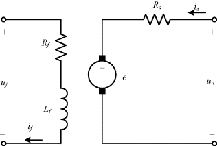
An equivalent circuit of a separately excited DC motor is shown on Figure 2.1. The armature side of the motor is modeled using an ideal voltage source (back EMF) and an armature resistance. The excitation circuit is represented by a field resistor and an inductor. The two circuits are fed by separate voltage sources.
Figure 2.1 An equivalent circuit of a separately excited DC motor

The mathematical model of the separately excited DC motor can be represented as [1–5]
(2.1) ![]()
(2.2) ![]()
(2.3) ![]()
where ua, uf, ia, and if are armature voltage, field voltage, armature current, and field current, respectively; Ra, Rf are armature and field resistances; La is armature inductance; J is machine inertia; ωr is rotor angular speed; ψf is field flux; e is electromagnetic force induced in the armature; and tl is the load torque.
The induced voltage ...
Get High Performance Control of AC Drives with Matlab / Simulink Models now with the O’Reilly learning platform.
O’Reilly members experience books, live events, courses curated by job role, and more from O’Reilly and nearly 200 top publishers.

