9.8 Motor Control Problems in the Drive with Filters
9.8.1 Introduction
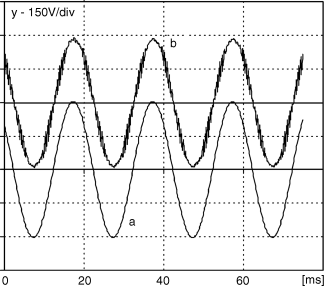
The differential mode motor filter has considerable influence on the control process. This is because each filter adds a voltage drop and a phase shift between the current and voltages on the filter input and output. For example, a typical LC filter for a 5.5 KW motor, under nominal load and frequency, gives ca. 5% and 5 degrees of voltage drop and phase shift, respectively. An example of real voltages on the filter input and output are presented in Figure 9.54.
Figure 9.54 Drive with LC filter – waveforms of: (a) commanded inverter output voltage; and (b) real motor supply voltage
As a result, most of the sophisticated sensorless drives cannot work properly when the filter is installed. It is also necessary to take into account the filter's components in the control process.
The general concept is to extend the corresponding steering algorithm with its subordinated control system for some of the filter state variable controls.
A differential mode LC filter is a two-dimensional linear stationary controlled system. The controlled state variables are motor supply voltage us and inverter output current i1, whereas the control quantity is an inverter output voltage u1. Current i1 represents the filter's internal variables.
The basic structure of the LC filter control system is presented in Figure 9.55.
Get High Performance Control of AC Drives with Matlab / Simulink Models now with the O’Reilly learning platform.
O’Reilly members experience books, live events, courses curated by job role, and more from O’Reilly and nearly 200 top publishers.

