3.4 LTE
3.4.1 Architecture
LTE system architecture is shown in Figure 3.27.
Figure 3.27 LTE architecture [72].
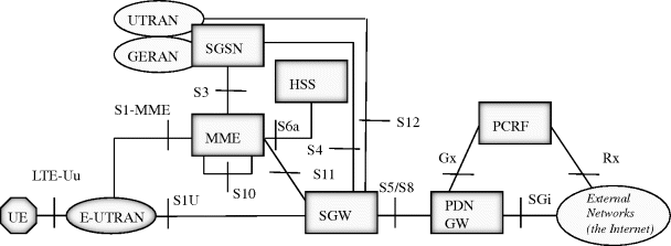
In the LTE system, the radio access network is called E-UTRAN (Evolved UTRAN). LTE is a packet switched network with no native support for circuit switched services. Instead, services of a circuit switched nature, e.g. voice, can be supported through the use of guaranteed bit rate bearers. The core network is clearly divided into a control plane entity MME (Mobility Management Entity) and a user plane entity consisting of a SGW (Serving Gateway) and a PDN GW (Packet Data Network Gateway).
E-UTRAN interfaces the core network elements via S1-U in the user plane, and via S1-MME in the control plane. MME is responsible for managing the bearers, authenticating the UEs, and managing mobility. The role of MME is comparable to that of the SGSN control plane.
In the user plane, SGW interfaces the radio network (eNodeB). It is the anchor point to the inter-eNodeB mobility and for handovers towards 2G and 3G systems. This is comparable to the SGSN user plane functionality. PDN GW interfaces the LTE system to the external networks, and it allocates IP addresses to the UEs. This is comparable to the GGSN role of 2G and 3G networks.
MME has an interface for the Home Subscriber Server (HSS), which stores subscriber information. HSS also supports the authentication of the subscriber, ...
Get Mobile Backhaul now with the O’Reilly learning platform.
O’Reilly members experience books, live events, courses curated by job role, and more from O’Reilly and nearly 200 top publishers.

