Appendix: Modeling and Analysis of the Combination-Wave Generator Used for Surge Testing (EN 61000-4-5)
The CWG Circuit
The CWG circuit was shown in Fig. 11.9. That is the one to refer here.
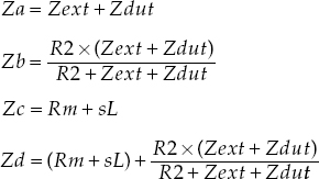
From Fig. 11.9 we see that in the s-plane
Mathematical Analysis
At time t = 0, the capacitor C is fully charged (to Vdc). The initial condition of the cap is described as a step function:
At the very moment the switch is thrown, we also assume that the applied-voltage source, Vdc, is simultaneously removed. This is equivalent to assuming a large enough ...
Get Power Over Ethernet Interoperability Guide now with the O’Reilly learning platform.
O’Reilly members experience books, live events, courses curated by job role, and more from O’Reilly and nearly 200 top publishers.

