Appendix B
Predictive Control Simulation—Torque Control of an Induction Machine Fed by a Two-Level Voltage Source Inverter
Figure B.1 shows the MATLAB®/Simulink® model used for simulation of the predictive torque control (PTC) of an induction machine fed by a two-level voltage source inverter described in Chapter 8. The simulation diagram contains six main elements: reference speed generation, PI speed controller, predictive control algorithm, inverter model, coordinate transformation, and induction machine model.
Figure B.1 Simulink model for the predictive torque control of an induction machine
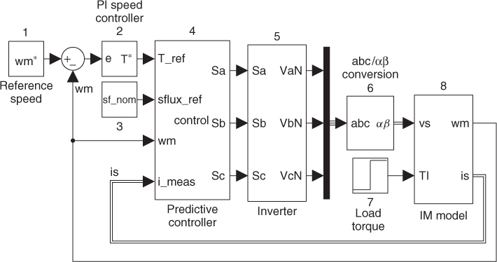
The reference speed (block 1) in the simulation layout can be a constant, a step block, or any other signal according to the simulation needs. For the reference speed tracking, a PI controller (block 2) is used. The PI controller receives the error signal and computes the torque reference for the predictive controller. Figure B.2 shows a discrete-time implementation of the PI controller. There are two tuning parameters in this controller: the proportional gain Kp and the integral gain Ki. For the design of these parameters, the transfer function between the rotor speed and the electrical torque is obtained from (8.12) through application of the Laplace transform:
Figure B.2 PI speed ...
Get Predictive Control of Power Converters and Electrical Drives now with the O’Reilly learning platform.
O’Reilly members experience books, live events, courses curated by job role, and more from O’Reilly and nearly 200 top publishers.

