5.4 Predictive Current Control Method
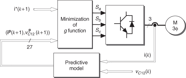
The predictive control scheme for the NPC inverter is shown in Figure 5.7. The future values of the load currents and voltages in the capacitors are predicted for the 27 switching states generated by the inverter, by means of (5.17), (5.11), and (5.12). For this purpose, it is necessary to measure the present load currents and voltages in the capacitors. After obtaining the predictions, a cost function g is evaluated for each switching state. The switching state that minimizes the cost function is selected and applied during the next sampling period.
Figure 5.7 Predictive current control method for the NPC inverter (Vargas et al., 2007 © IEEE)
The control requirements for the NPC inverter are:
- Load current reference tracking
- DC link capacitor voltages balance
- Reduction of the switching frequency.
These requirements can be formulated in the form of a cost function to be minimized. The cost function for the NPC inverter has the following composition:
The first two terms are the load current errors in orthogonal coordinates, where ![]() and
and ![]() are ...
are ...
Get Predictive Control of Power Converters and Electrical Drives now with the O’Reilly learning platform.
O’Reilly members experience books, live events, courses curated by job role, and more from O’Reilly and nearly 200 top publishers.

