FTDI AS THE USB INTERFACE TO A SYSTEM
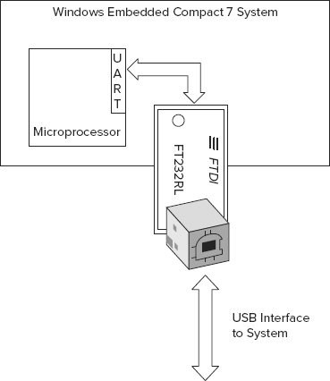
As explained before, one usage scenario for the FTDI device was where the system microprocessor has a spare UART that can connect to the FTDI, as shown in Figure 44-6. Generally for development boards this is not an option because there are no spare UARTs because they are usually all fully implemented as RS232 ports. If developing a new board, then an FTDI integrated circuit could be included in the design. Why would you do so when many embedded microprocessors already have USB ports? The answer is because it saves having to develop a USB driver.
The FTDI driver is not part of the BSP because this is needed on the host end of the USB. A BSP driver would need to be developed that implements a serial protocol over the UART for interacting with the Compact 7 system.
The registry settings for the driver include a VendorID (VID) and a ProductID (PID). For systems that use an FTDI integrated circuit, although the VID must always identify FTDI in the driver’s registry setting, FTDI can grant OEMs unique PIDs that identify its product. If this is the case, typically a system would use the D2XX driver and implement custom functionality.
For development purposes, there are development modules such as the UM232R. These modules implement the ancillary USB circuitry plus a USB connector. The UART connectivity is provided as some pins. That ...
Get Professional Windows® Embedded Compact 7 now with the O’Reilly learning platform.
O’Reilly members experience books, live events, courses curated by job role, and more from O’Reilly and nearly 200 top publishers.

