Chapter 9. Controlling Hardware
9.0. Introduction
In this chapter, you come to grips with the control of electronics through the Raspberry Pi’s GPIO connector.
Most of the recipes require the use of solderless breadboard and male-to-female and male-to-male jumper wires (see Recipe 8.10).
9.1. Connecting an LED
Note
Be sure to check out the accompanying video for this recipe at http://razzpisampler.oreilly.com.
Problem
You want to know how to connect an LED to the Raspberry Pi.
Solution
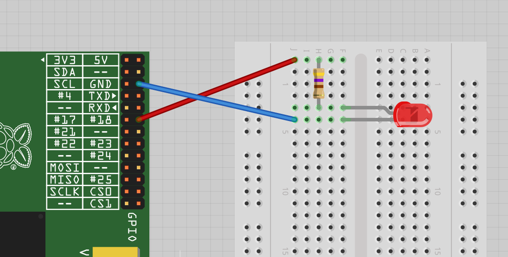
Connect an LED (see Opto-Electronics) to one of the GPIO pins using a 470Ω or 1kΩ series resistor (see Resistors and Capacitors) to limit the current. To make this recipe, you will need:
- Breadboard and jumper wires (see Prototyping Equipment)
- 1kΩ resistor (see Resistors and Capacitors)
- LED (see Opto-Electronics)
Figure 9-1 shows how you can wire this using solderless breadboard and male-to-female jumper leads.
Having connected the LED, we need to be able to turn it on and off using commands from Python. To do this, follow Recipe 8.3 to install the RPi.GPIO Python library.
Start a Python console (Recipe 5.3) from the Terminal with superuser access and enter these commands:
$sudopython>>>importRPi.GPIOasGPIO>>>GPIO.setmode(GPIO.BCM)>>>GPIO.setup(18,GPIO.OUT)>>>GPIO.output(18,True)>>>GPIO.output(18,False)
This will turn your LED on and off.
Discussion ...
Get Raspberry Pi Cookbook now with the O’Reilly learning platform.
O’Reilly members experience books, live events, courses curated by job role, and more from O’Reilly and nearly 200 top publishers.

