Whereas the data acquisition part of an instrumentation system senses the physical world and provides input data, the control part of an instrumentation system uses that data to effect changes in the physical world. Control of a physical device involves transforming some type of command or sensor input into a form suitable to cause a change in the activity of that device. More specifically, control entails generating digital or analog signals (or both) that may be used to perform a control action on a device or system. Linear control systems can be broadly grouped into two primary categories, open-loop and closed-loop, depending on whether or not they employ the concept of feedback.
Another common type of control system, the sequential control, utilizes time as its primary control input. In a sequential system, events occur at specific times relative to a primary event, and each event is typically discrete. In other words, a sequential event is either on or off, active or inactive. A computer is, by its very nature, a form of sequential controller, and sequential controls can usually be modeled using state machines. We’ll look at state diagrams in Chapter 8.
We will encounter all three types of control systems in this book. Chapter 9 goes into the theory behind them in more detail, but for now, a high-level overview will suffice to set the stage.
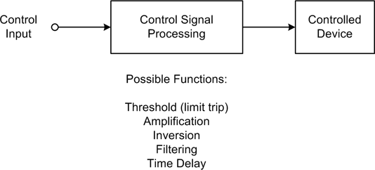
In an open-loop scheme, there is no feedback between the output and the control input of the system. In other words, the system has no way to determine if the control output actually had the desired effect. However, this doesn’t prevent it from being useful. The accuracy of an open-loop control system depends on the accuracy of its components and how well the system models what it is controlling. Figure 1-3 shows a simple block diagram of an open-loop control system. The block labeled “Controlled Device” might be an electric motor, a lamp, a fan, or a valve. While it might appear that there isn’t much going on here, open-loop controls can actually entail a high degree of complexity and they are fairly common.
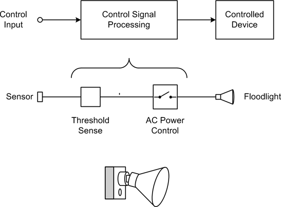
Even though an open-loop control system is “blind,” in a sense, it can still incorporate time into its design. An automatic light switch is one possible real-world example. A greatly simplified diagram of such a device is shown in Figure 1-4.
These popular devices contain a sensor (typically infrared) that will activate a floodlight if something appears in the field of view of the sensor. There is no feedback to ensure that the lights actually come on (at least, not in the typical units for residential use), nor can the sensor easily distinguish between a burglar and a large housecat.
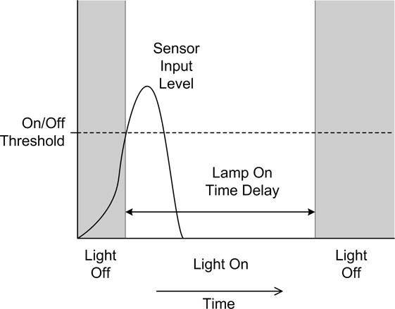
An automatic light does, however, have a built-in time delay to hold the light on for a period of time after the sensor’s input threshold has been crossed; otherwise, it would just turn on and then immediately turn back off again when the sensor input dropped back below the threshold. This is shown in the diagram in Figure 1-5. If there were no time delay to hold the lamp on, a large housecat hopping up and down in front of the sensor would cause the light to flash on and off repeatedly. This would probably annoy the neighbors (then again, automatic lights with excessive time delays can annoy the neighbors as well).
A closed-loop control scheme utilizes data obtained from the device or system under control, known as feedback, to determine the effect of the control and modify the control actions in accordance with some internal algorithm (also known as the “control laws”). Figure 1-6 shows a block diagram of a basic closed-loop control system.
Notice that the control input and the feedback signal are summed with opposing signs at the circle symbol in Figure 1-6, which is called a “summing junction” or “summing node.” The output is called the control error. This is because the key to a closed-loop control is the response of the controlled device to the control signal generated by the block labeled “Control Signal Processing.” The control error is input to the control signal processing block, and the system will attempt to drive its control output into the controlled device to whatever extent is needed or possible in order to make the control error zero. Those readers who are familiar with operational amplifier (op amp) circuits will recognize this immediately: it’s the same principle that op amp circuits are based on.
As one might suspect, there is more going on here than the system diagram in Figure 1-6 shows. Both the control and feedback processing blocks may have some degree of amplification (gain) incorporated into their design. They may also include attenuation, filters, or limit thresholds. Gain levels are selected based on the application, and responses may even be nonlinear if necessary.
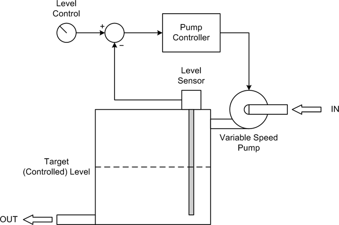
Here’s a somewhat more interesting closed-loop control example. Let’s assume that we want to maintain a constant fluid level in a storage tank while its contents are removed at varying rates. At some times the drain rate may be quite high, while at other times it may be very low or even zero. Figure 1-7 shows the setup and its associated control loop.
A sensor measures the fluid level in the tank, and if it is below the commanded value the rate of the input pump is commanded to increase so more fluid will enter the tank. As the fluid level approaches the target setting, the rate of the pump decreases, and once the target is reached it stops completely. This arrangement will automatically compensate for changes in how fast the fluid is drawn off from the tank, so long as the drain rate does not exceed the ability of the pump to keep up with it.
Sequential controls are a very common form of control system and are straightforward to implement. Automated packaging systems, such as those used to form cereal boxes or fill plastic bags with animal feed, are typically timed sequential controls that perform specific actions using electrical or pneumatic actuators. Other sequential controls might employ some type of sensing to change sequences as necessary, or to sense a fault condition and halt the system.
Figure 1-8 shows the timing diagram for a sequential AC power controller with five devices. In this example, a delay after each device is powered on allows it to stabilize and respond to a query to verify that it is functioning correctly. In a system such as this, each device would typically have three possible states: On, Off, and Fail. In addition to commanding the devices on or off in a timed sequence, the controller would also check each device to verify that it powered up correctly. Should a device fail, the controller would either halt the sequence or begin an automatic shutdown by disabling the devices already enabled, in reverse order.
Get Real World Instrumentation with Python now with the O’Reilly learning platform.
O’Reilly members experience books, live events, courses curated by job role, and more from O’Reilly and nearly 200 top publishers.


