8.3 Open Architecture Tactical Protocol Stack Model
Figure 8.2 introduces a tactical wireless networking open architecture model. The figure shows the stack layers for two peer nodes. The layers above the plain text IP layer (application layer, session layer, and transport layer) are not shown. We assume that COTS applications or non-COTS applications will be used with standard IP ports that use standard TCP over IP or UDP over IP. Here, “applications” refer to the application layer, the session layer, and the transport layer in Figure 1.1. The radio layer represents all the layers below the cipher text IP layer (or the DLL, MAC, and physical layers in Figure 1.1). Each radio can have its own implementation of these layers (or a different mutation of these layers as with the WNW and SRW). The peer-to-peer relationship of the radio layer is expressed by the horizontal arrows, VII in Figure 8.2, to indicate that within the same subnet, the different radio layers can peer with each other.
Figure 8.2 Tactical wireless model with well-defined entities and ICDs.
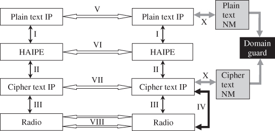
The IV arrow in Figure 8.2 indicates the cross layer signaling between the radio and the cipher text IP layers. Cross layer signaling between the cipher text and plain text IP layers can be allowed, if approved by NSA (in the USA), and could be processed through network management (NM) entities that relay this information through ...
Get Tactical Wireless Communications and Networks: Design Concepts and Challenges now with the O’Reilly learning platform.
O’Reilly members experience books, live events, courses curated by job role, and more from O’Reilly and nearly 200 top publishers.

