8 Tunable External-Cavity Semiconductor Lasers 37S
media or by going to tapered-stripe gain media. Recently, up to -1W output has
been obtained from an external cavity laser with a tapered-stripe gain medium
[43]. The output beam was described as diffraction-limited. The coupling effi-
ciency to optical fiber was not reported.
5. FEEDBACK MODEL
5.1 Effective Reflectance
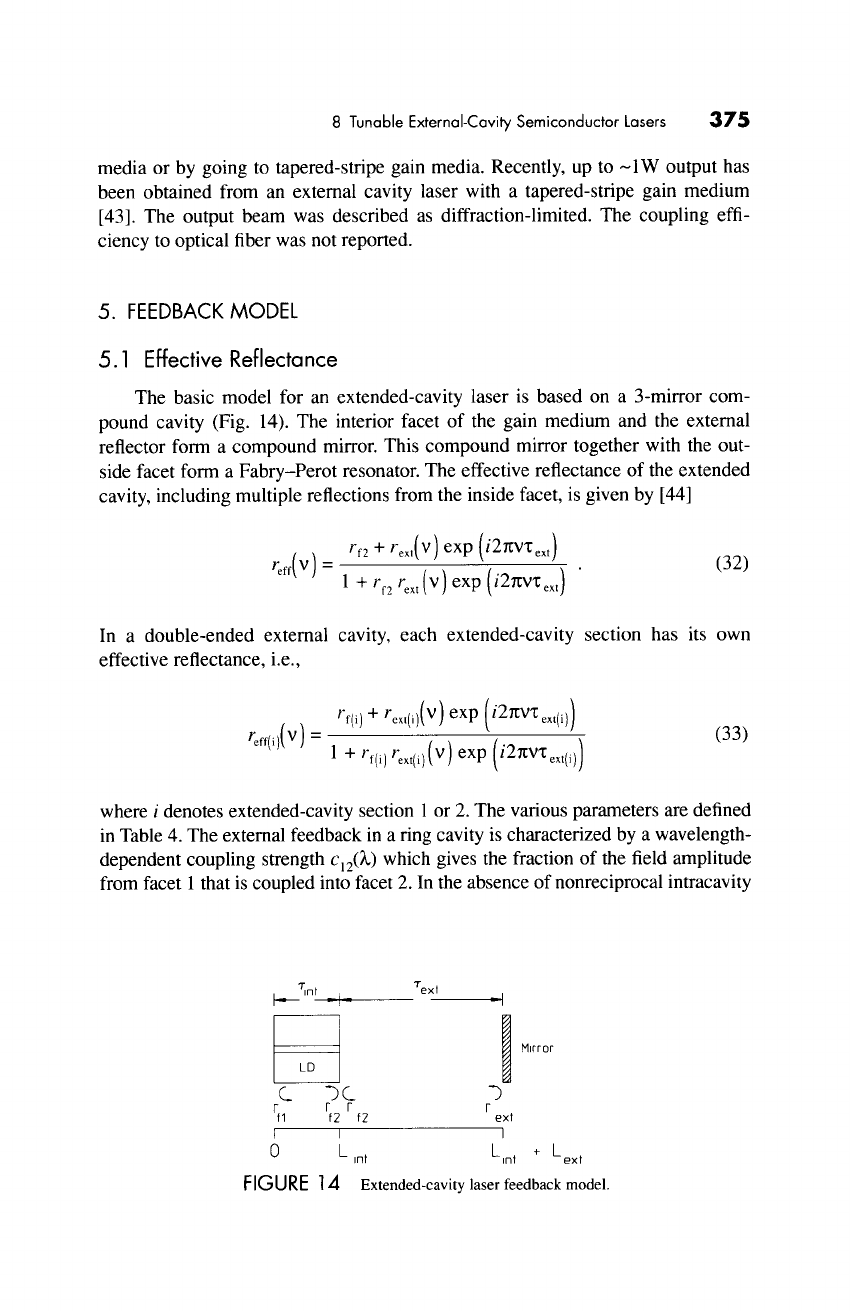
The basic model for an extended-cavity laser is based on a 3-mirror com-
pound cavity (Fig. 14). The interior facet of the gain medium and the external
reflector form a compound mirror. This compound mirror together with the out-
side facet form a Fabry-Perot resonator. The effective reflectance of the extended
cavity, including multiple reflections from the inside facet, is given by [44]
rf2 + rext(V) exp (i2%'VX ext)
reef(V) = 1 + rf2 rex t (v)
exp (i2gV~ext) " (32)
In a double-ended external cavity, each extended-cavity section has its own
effective reflectance, i.e.,
rf(i) + rext(i)(v) exp (i2~VT'ext(i))
Feff(i)(V) = 1 "+" Kf(i)Fext(i)(V ) exp
(i2~V'l;ext(,))
(33)
where i denotes extended-cavity section 1 or 2. The various parameters are defined
in Table 4. The external feedback in a ring cavity is characterized by a wavelength-
dependent coupling strength C l20~) which gives the fraction of the field amplitude
from facet 1 that is coupled into facet 2. In the absence of nonreciprocal intracavity
i Tint ~_ Text
I ~ "IIDt
Lol
1
C bC "3
r r r r
fl f2 f2 ext
I I I
O L L +L
int ~nt ext
FIGURE 14
Extended-cavity laser feedback model.
376 Paul Zorabedian
elements such as an optical isolator, the coupling between the two facets obeys
reciprocity, i.e., c12(~) = c21(~). Multiple reflections between the facets and the
external mirrors defining the ring can be neglected because there are no (inten-
tional) standing waves in the cavity. However, sometimes spurious etalons exist
between the residual reflections of the facets and the intracavity optics.
5.2 Threshold Current
The gain coefficient per unit length is given by
g(',~,) = 711- Itr(~,)] , (34)
where "t is a constant independent of ~, I is the pump current, and Itr(~) is the
transparency current. Note that the previously-defined confinement factor F has
been lumped in with the constant % The threshold magnitude condition states
that the round-trip gain equals the total round-trip loss. This leads to the follow-
ing general expression for the threshold current:
Ith "- ~[0~ int -I- O~ mir] -I- Itr , (35)
where
O~mi r
is represents the mirror loss for the appropriate cavity configuration.
These are given below.
5.3 Mirror
Losses
The mirror loss in an extended-cavity configuration is given by
1'hi 1 /
mir-- Lint rf,roff( )
(36)
TABLE 4 External Feedback Model Parameters
rfl, rf2
v
rextl (v), rext2(v)
6'
"l;ext 1 -" c/2Lext 1
"l;ext2 = c/2Lext2
Amplitude reflectances of facets
Optical frequency
Amplitude reflectances of extended cavity sections (lumping, coupling, filter,
and mirror losses)
Speed of light
Round-trip time of extended cavity section with length Lextl
Round-trip time of extended cavity section with length Lext2
Get Tunable Lasers Handbook now with the O’Reilly learning platform.
O’Reilly members experience books, live events, courses curated by job role, and more from O’Reilly and nearly 200 top publishers.

