Component Views
UML uses two views of components, a black-box view and a white-box view. The black-box view shows a component from an outside perspective; the white-box view shows how a component realizes the functionality specified by its provided interfaces.
Black-Box View
The black-box view of a component shows the interfaces the component provides, the interfaces it requires, and any other detail necessary to explain the guaranteed behavior of the component. It does not specify anything about the internal implementation of the component. This distinction is central to the concept of replaceable components.
Assembly connectors
When modeling a black-box view of a component, you represent the provided and required interfaces using assembly connectors . Assembly connectors are illustrated using ball-and-socket icons. To show a required interface, use the socket icon and write the name of the interface near the connector symbol. Figure 5-3 shows a component with two required interfaces.
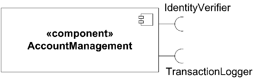
Figure 5-3. Component with two required interfaces
Show a provided interface with the ball half of an assembly connector, again with the name of the interface near the symbol. Figure 5-4 shows a component with a provided interface.
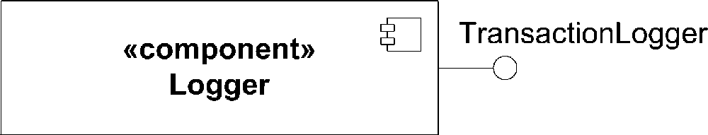
Figure 5-4. Component with a provided interface
To wire components together, ...
Get UML 2.0 in a Nutshell now with the O’Reilly learning platform.
O’Reilly members experience books, live events, courses curated by job role, and more from O’Reilly and nearly 200 top publishers.

