Chapter 6. Deployment Diagrams
Deployment diagrams model the mapping of software pieces of a system to the hardware that is going to execute it. Software elements (components, classes, etc.) are typically manifested using artifacts and are mapped to the hardware or software environment that will host them, called nodes. Because many nodes may be associated with the deployment of a system, communication between nodes can be modeled using communication paths.
Artifacts
Artifacts represent physical pieces of information related to the software development process. For example, you can use an artifact to represent a DLL needed by your system, a user's manual, or an executable produced when your software is compiled.
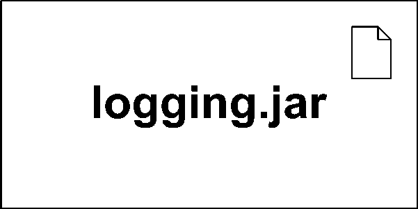
Typically artifacts are used to represent the compiled version of a component (see Chapter 5); however, UML 2.0 allows artifacts to represent any packageable element, which includes just about everything in UML. You show an artifact using the classifier rectangle with a dog-eared paper in the upper right. Figure 6-1 shows a basic artifact.

Figure 6-1. A simple artifact
UML allows artifacts to have properties and operations that manipulate the artifact. These are most commonly used when an artifact represents a set of configurable options. For example, deployment specifications , which represent configuration settings for deployed artifacts, frequently use attributes to ...
Get UML 2.0 in a Nutshell now with the O’Reilly learning platform.
O’Reilly members experience books, live events, courses curated by job role, and more from O’Reilly and nearly 200 top publishers.

