Chapter 7. Use Case Diagrams
Use cases are a way to capture system functionality and requirements in UML. Use case diagrams consist of named pieces of functionality (use cases ), the persons or things invoking the functionality (actors), and possibly the elements responsible for implementing the use cases (subjects ).
Use Cases
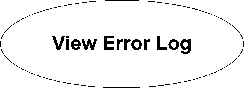
Use cases represent distinct pieces of functionality for a system, a component, or even a class. Each use case must have a name that is typically a few words describing the required functionality, such as View Error Log. UML provides two ways to draw a use case. The first is an oval with the name of the use case in the center. Figure 7-1 shows a basic use case.

Figure 7-1. A simple use case
You can divide a use case's oval into compartments to provide more detail about the use case, such as extension points (see "Use Case Extension"), included use cases (see "Use Case Inclusion"), or the modeling of specific constraints. Figure 7-2 shows a use case oval with a compartment listing extension points.
However, the oval representation of use cases doesn't hold up well with detailed compartments. UML recommends you use the classifier notation if you want to provide details about a use case. Show the use case as a rectangle, with the use case oval in the top-right corner. Now, place the name of the use case in the top, in bold. You can then divide the classifier ...
Get UML 2.0 in a Nutshell now with the O’Reilly learning platform.
O’Reilly members experience books, live events, courses curated by job role, and more from O’Reilly and nearly 200 top publishers.

