3.2 PIPELINING OF FIR DIGITAL FILTERS
Consider the pipelined implementation of the 3-tap FIR filter of (3.1) obtained by introducing 2 additional latches as shown in Fig. 3.3.
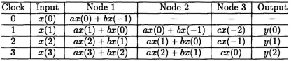
The critical path is now reduced from TM + 2TA to TM + TA. In this arrangement while the left adder initiates the computation of the current iteration the right adder is completing the computation of the previous iteration result. The schedule of events for this pipelined system is shown in Table 3.1. In this system, at any time, 2 consecutive outputs are computed in an interleaved manner.
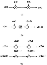
Fig. 3.2 (a) A datapath. (b) The 2-level pipelined structure of (a). (c) The 2-level parallel processing structure of (a).
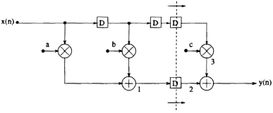
Fig. 3.3 Pipelined FIR filter. The dashed vertical line represents a feed-forward cutset.
Table 3.1 Schedule of Events in the Pipelined FIR Filter in Fig. 3.3
One must note that in an M-level pipelined system, the number of delay elements in any path from input to output is (M − 1) greater than that in the same path in the original sequential circuit. While pipelining reduces the critical path, it leads to a penalty in terms of an increase in latency. Latency essentially is the difference in ...
Get VLSI Digital Signal Processing Systems: Design and Implementation now with the O’Reilly learning platform.
O’Reilly members experience books, live events, courses curated by job role, and more from O’Reilly and nearly 200 top publishers.

