7.3 FIR SYSTOLIC ARRAYS
This section derives a family of systolic arrays for FIR digital filters using the linear mapping technique.
7.3.1 Design B1 (Broadcast Inputs, Move Results, Weights Stay)
The systolic design B1 is derived by selecting the projection vector, processor vector, and scheduling vector as follows:
![]()
Using these definitions, we can show that:
- Any node with index IT = (i, j) is mapped to processor
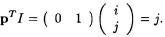
Therefore, all nodes on a horizontal line are mapped to the same processor.
- Any node with index IT = (i, j) is executed at time
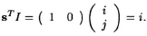
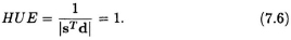
- Since
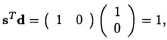
then
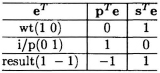
- Edge mapping: The 3 fundamental edges corresponding to weight, input, and result can be mapped to corresponding edges in the systolic array according to Table 7.1.
Table 7.1 Edge Mapping Table for Design B1
The block diagram of B1 systolic array design is then constructed as shown in Fig. 7.3. The low-level implementation of ...
Get VLSI Digital Signal Processing Systems: Design and Implementation now with the O’Reilly learning platform.
O’Reilly members experience books, live events, courses curated by job role, and more from O’Reilly and nearly 200 top publishers.

