Chapter 6. Peer-to-peer Q replication on AIX platforms 547
Figure 6-2 Overview of setup steps
6.5.1 Step 1: Install WebSphere MQ, WebSphere II with Q replication
Refer to IBM WebSphere MQ for AIX Quick Beginnings Version 5.3,
GC34-6076-02; and IBM DB2 Information Integrator Installation Guide for Linux,
Unix and Windows Version 8.2, GC18-7036-01, for details on prerequisites and
steps for installing WebSphere MQ and WebSphere II with Q replication,
respectively.
6.5.2 Step 2: Determine topology
We chose the peer-to-peer replication topology to address the Luna business
requirement, as described in 6.3, “Rationale for the peer-to-peer solution” on
page 545.
6.5.3 Step 3: Collect topology and configuration information
Implementing peer-to-peer replication is a complex task involving effective
coordination of the configuration settings of the operating system, database
management system, WebSphere MQ and WebSphere Information Integrator Q
replication offerings.
STEP 3: Collect topology & configuration information for WebSphere MQ & Q replication
STEP 2:
Determine toplogy (unidirectional, bidirectional or peer-to-peer)
STEP 1:
Install WebSphere MQ, WebSphere II with Q replication & verify successful install
STEP 4: Setup userids, privileges, and database servers
STEP 7:
Set up WebSphere MQ and Q replication monitoring environment (GUI or commands)
STEP 5:
Configure WebSphere MQ & verify successful configuration
STEP 6: Configure & activate Q replication (GUI or commands)
548 WebSphere Information Integrator Q Replication: Fast Track Implementation Scenarios
Towards this end, we have developed a template that identifies all the
information required to implement a peer-to-peer replication topology, and the
cross-relationships between the information elements to ensure a smooth
implementation.
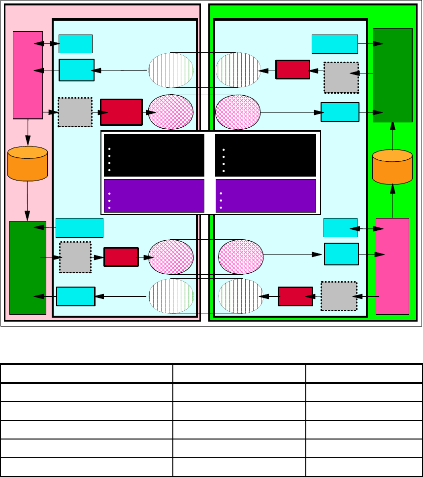
Figure 6-3 provides a high-level overview of the various objects involved in
implementing a peer-to-peer replication topology involving two servers, and
serves as a reference for the host and DB2 system information template
(Table 6-1 on page 549), WebSphere MQ configuration information template
(Table 6-2 on page 550), Q replication configuration information template
(Table 6-3 on page 552), and Replication Alert Monitor configuration information
template (Table 6-4 on page 553). Each of the information elements for each
server is associated with a reference identification such as A.7a or B.7b, where A
represents one of the servers and B the other server. These reference IDs are
then cross-referenced in the template itself as well as the WebSphere II Q
replication configuration screens and scripts. For example, in Table 6-2 on
page 550 on WebSphere MQ information, for the XMITQ parameter (reference
ID A.18a for Server A) in the SendQ, we require reference ID A.13 (which is the
name of the TransmitQ), and that value is QM_WEST.
Once all the information identified in the template had been collected, we can
proceed with the actual implementation.
We have collected all the identified information for the Luna peer-to-peer
replication implemented and recorded them in the templates Table 6-1 on
Important: To ensure successful and error-free implementation, we strongly
encourage systematic and careful planning that involves identifying and
gathering all required information prior to commencing implementation.
Attention: In Figure 6-3, there appear to be two sets of transmission queues,
and sender and receiver channels, on each server. However, there is only one
set on each server, as can be deduced from the identical names. Figure 6-3
has the appearance of two sets so that the flow of data and messages
between the two servers is easily understood.
Note: The template shows certain parameter values that are required for Q
replication (such as parameter DEFPSIST
must be set to YES for the
TransmitQ [reference ID A.13] and does
not have a reference ID), while others
can be customized for a particular environment (such as reference ID A.13d
parameter MAXDEPTH
may be set to any value).
Chapter 6. Peer-to-peer Q replication on AIX platforms 549
page 549, Table 6-2 on page 550, Table 6-3 on page 552, and Table 6-4 on
page 553. We are now ready to proceed with configuring the various resources.
Figure 6-3 Peer-to-peer replication topology objects overview
Table 6-1 Host and DB2 system information
Description Server A Server B
Host name (A.1) JAMESBAY (B.1) AZOV
Host IP address (A.2) 9.1.39.79 (B.2) 9.1.39.89
DB2 subsystem name or instance owner (A.3) db2inst1 (B.3) db2inst1
DB2 group name (z/OS only) (A.4) (B.4)
DB2 location name (z/OS only) (A.5) (B.5)
QCAPTURE
ServerA
Schema
ServerB
SpillQ
ServerA
Remote
SendQ
ServerB
ReceiveQ
TransmitQ
B2A
"SDR"
channel
B2A
"RCV"
channel
B2A
"RCV"
channel
A2B
"SDR"
channel
A2B
ServerA
Listener port
TransmitQ
A2B
QAPPLY
ServerB
Schema
ServerB
Listener port
ServerA Host name or IP Address
ServerA Queue Manager
ServerB
DB2 Instance
database
ServerB Host name or IP Address
ServerB Queue Manager
ServerA
DB2 Instance
database
QAPPLY
ServerA
Schema
ServerB
Remote
SendQ
TransmitQ
B2A
"SDR"
channel
B2A
"RCV"
channel
B2A
ServerA
SpillQ
ServerA
ReceiveQ
"SDR"
channel
A2B
Subcription (SUBB2A)
ServerA table details
ServerB table details
Replication queue map (RQMB2A)
Replication Queue Map (RQMB2A)
ServerB Remote SendQ
ServerA ReceiveQ
ServerA Remote AdminQ
Queue Map options
Replication Queue Map (RQMA2B)
ServerA Remote SendQ
ServerB ReceiveQ
ServerB Remote AdminQ
Queue Map options
Subcription (SUBA2B)
ServerA table details
ServerB table details
Replication queue map (RQMA2B)
ServerA
AdminQ
ServerA
RestartQ
ServerB
Remote
AdminQ
ServerB
Schema
ServerB
RestartQ
QCAPTURE
ServerB
AdminQ
ServerB
Listener port
ServerA
Listener port
"RCV"
channel
A2B
TransmitQ
A2B
ServerA
Remote
AdminQ

Get WebSphere Information Integrator Q Replication: Fast Track Implementation Scenarios now with the O’Reilly learning platform.

O’Reilly members experience books, live events, courses curated by job role, and more from O’Reilly and nearly 200 top publishers.