7
Common Control Loops
This chapter will describe some common loops encountered in process control. The loop characteristics, type of controller to use, response, tuning and limitations will all be examined.
7.1 Flow Loops
A typical flow control loop is shown in Figure 7.1. This process responds very fast and, even for long lengths of pipe, the dead time and the capacitance are very small. Typically the process response is limited by the valve response (time constant).
Figure 7.1 Flow control loop.
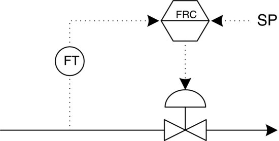
As shown in Figure 7.1, the flow sensor/transmitter is always placed upstream of the valve for several reasons. First, many flow-measuring devices have upstream and downstream straight run pipe requirements. Usually, the upstream straight run is longer than the downstream straight run. Therefore, the flow-measuring device can be placed closer to the valve upstream than downstream, where there might be problems with additional pressure drop through piping if a head flow device is used. Some examples of head flow devices are orifice plates, venturi tubes and flow nozzles. Second, when the flow sensor is upstream from the valve there is a more constant inlet pressure since it is closer to the source. Finally, there might be pressure fluctuations introduced to elements installed downstream from the valve as a result of valve stroking. Valve stroking results when the valve moves up and ...
Get A Real-Time Approach to Process Control, 3rd Edition now with the O’Reilly learning platform.
O’Reilly members experience books, live events, courses curated by job role, and more from O’Reilly and nearly 200 top publishers.

