12A Walk‐through Example of the Basic Fleet Assignment Model
12.1 Problem Definition
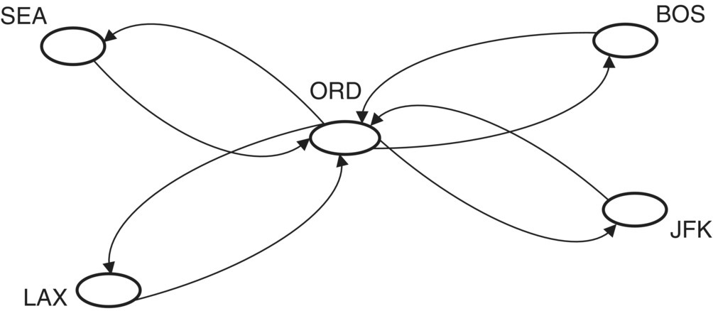
In this chapter, an example is presented to further explain the formulation of the basic fleet assignment model, which is presented in Chapter 11. For this purpose, we assume a small hypothetical airline. This airline has a hub at Chicago O’Hare Airport (ORD) and serves four airports including Boston Logan International Airport (BOS), John F. Kennedy International Airport (JFK), Los Angeles International Airport (LAX), and Seattle–Tacoma International Airport (SEA). Each of these four cities is served by two round trips to and from the hub. Thus, the schedule includes 16 flights that are either originating from or ending at the hub. Assume that the airline has two fleet types, namely, e1 and e2. The number of aircraft in each fleet type is assumed to be known. The scheduled departure time for these 16 flights is also given. The arrival time of each flight depends on whether the flight is assigned to fleet e1 or e2. Figure 12.1 shows the network structure of the hypothetical airline.

Figure 12.1 The network structure of a hypothetical airline with a hub at ORD.
Figures 12.2 and 12.3 show two time‐staggered diagrams that represent the schedule of the 16 flights when assigned to fleets e1 and e2, respectively. Each flight is represented by an arrow that connects between two stations. The flight ...
Get Airline Network Planning and Scheduling now with the O’Reilly learning platform.
O’Reilly members experience books, live events, courses curated by job role, and more from O’Reilly and nearly 200 top publishers.

