Chapter 6Architecture of the LTE Air Interface
Now that we have covered the principles of the air interface, we can explain how those principles are actually implemented in LTE. This task is the focus of the next five chapters.
In this chapter, we will cover the air interface's high-level architecture. We begin by reviewing the air interface protocol stack, and by listing the channels and signals that carry information between the different protocols. We then describe how the OFDMA and SC-FDMA air interfaces are organized as a function of time and frequency in a resource grid and discuss how LTE implements transmissions from multiple antennas using multiple copies of the grid. Finally, we bring the preceding material together by illustrating how the channels and signals are mapped onto the resource grids that are used in the uplink and downlink.
6.1 Air Interface Protocol Stack
Figure 6.1 reviews the protocols that are used in the air interface, from the viewpoint of the mobile. As well as the information presented in Chapter 2, the figure adds some detail to the physical layer and shows the information flows between the different levels of the protocol stack.
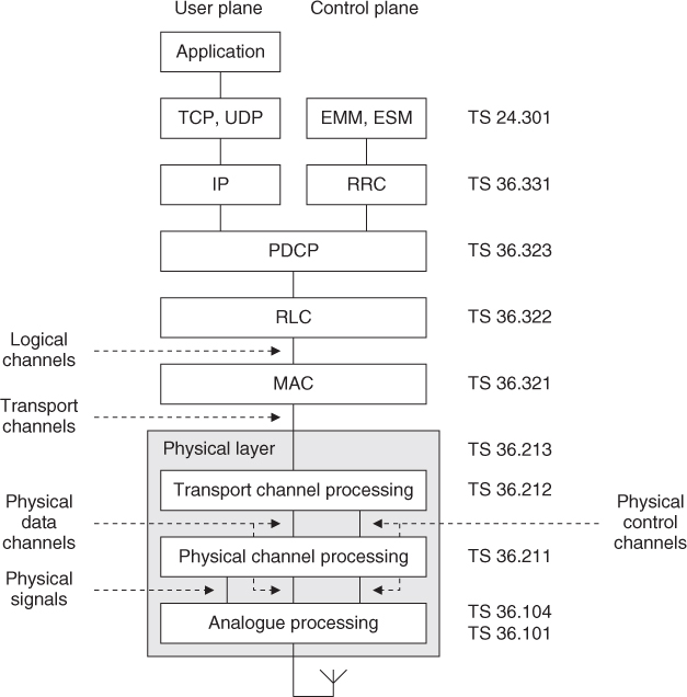
Figure 6.1 Architecture of the air interface protocol stack
Let us consider the transmitter. In the user plane, the application creates data packets that are processed by protocols such as TCP, UDP and IP, while in ...
Get An Introduction to LTE: LTE, LTE-Advanced, SAE, VoLTE and 4G Mobile Communications, 2nd Edition now with the O’Reilly learning platform.
O’Reilly members experience books, live events, courses curated by job role, and more from O’Reilly and nearly 200 top publishers.

