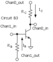
PB.4. Measurement of βDC versus the Collector Current

Components

Use RB and RC from PB.3.

Procedure

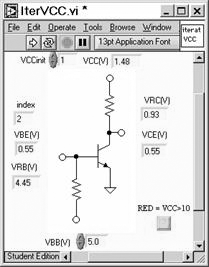
  • Connect Circuit B3 and run subVI, IterVCC.vi. The VI adjusts VCC to set VCE = VBE. Try various values of VBB at VCCinit = 1 V. Verify that the VI can adjust VCC to make VBE = VCE (VCB = 0). With a proper choice of resistors, as verified in PB.3, VCC ≈ 10V for VBB ≈ 10V. Beta_IC.vi sweeps VBB until ICmax ≈ 1mA (very approximately) or Chan0_out = 10 V.
  • Open Beta_IC.vi. Set values for RC and RB in the Digital Controls. Run the VI and re-run while ...

Get Analog Electronics with LabVIEW® now with the O’Reilly learning platform.

O’Reilly members experience books, live events, courses curated by job role, and more from O’Reilly and nearly 200 top publishers.