Chapter 4. Networking
This chapter looks at how cluster services such as Spark and Hadoop use the network and how that usage affects network architecture and integration. We also cover implementation details relevant to network architects and cluster builders.
Services such as Hadoop are distributed, which means that networking is a fundamental, critical part of their overall system architecture. Rather than just affecting how a cluster is accessed externally, networking directly affects the performance, scalability, security, and availability of a cluster and the services it provides.
How Services Use a Network
A modern data platform comprises of a range of networked services that are selectively combined to solve business problems. Each service provides a unique capability, but fundamentally, they are each built using a common set of network use cases.
Remote Procedure Calls (RPCs)
One of the most common network use cases is when clients request that a remote service perform an action. Known as remote procedure calls (RPCs), these mechanisms are a fundamental unit of work on a network, enabling many higher-level use cases such as monitoring, consensus, and data transfers.
All platform services are distributed, so by definition, they all provide RPC capabilities in some form or other. As would be expected, the variety of available remote calls reflects the variety of the services themselves—RPCs to some services last only milliseconds and affect only a single record, but calls to other services instantiate complex, multiserver jobs that move and process petabytes of information.
Implementations and architectures
The definition of an RPC is broad, applying to many different languages and libraries—even a plain HTTP transfer can be considered to be an RPC.
Data platform services are a loosely affiliated collection of open source projects, written by different authors. This means there is very little standardization between them, including the choice of RPC technology. Some services use industry-standard approaches, such as REST, and others use open source frameworks, such as Apache Thrift. Others, including Apache Kudu, provide their own custom RPC frameworks, in order to better control the entire application from end to end.
Services also differ widely in terms of their underlying architectures. For example, Apache Oozie provides a simple client-server model for submitting and monitoring workflows—Oozie then interacts with other services on your behalf. By contrast, Apache Impala combines client-server interactions over JDBC with highly concurrent server-server interactions, reading data from HDFS and Kudu and sending tuple data between Impala daemons to execute a distributed query.
Platform services and their RPCs
Table 4-1 shows examples of RPCs across the various services.
| Service | Client-server interactions | Server-server interactions |
|---|---|---|
ZooKeeper |
Znode creation, modification, and deletion |
Leader election, state replication |
HDFS |
File and directory creation, modification, and deletion |
Liveness reporting, block management, and replication |
YARN |
Application submission and monitoring, resource allocation requests |
Container status reporting |
Hive |
Changes to metastore metadata, query submission via JDBC |
Interactions with YARN and backing RDBMS |
Impala |
Query submission via JDBC |
Tuple data exchange |
Kudu |
Row creation, modification, and deletion; predicate-based scan queries |
Consensus-based data replication |
HBase |
Cell creation, modification, and deletion; scans and cell retrieval |
Liveness reporting |
Kafka |
Message publishing and retrieval, offset retrieval and commits |
Data replication |
Oozie |
Workflow submission and control |
Interactions with other services, such as HDFS or YARN, as well as backing RDBMS |
Process control
Some services provide RPC capabilities that allow for starting and stopping remote processes. In the case of YARN, user-submitted applications are instantiated to perform diverse workloads, such as machine learning, stream processing, or batch ETL, with each submitted application spawning dedicated processes.
Management software, such as Cloudera Manager or Apache Ambari, also uses RPCs to install, configure, and manage Hadoop services, including starting and stopping them as required.
Latency
Every call to a remote procedure undergoes the same lengthy process: the call creates a packet, which is converted into a frame, buffered, sent to a remote switch, buffered again within the switch, transferred to the destination host, buffered yet again within the host, converted into a packet, and finally handed to the destination application.
The time it takes for an RPC to make it to its destination can be significant, often taking around a millisecond. Remote calls often require that a response be sent back to the client, further delaying the completion of the interaction. If a switch is heavily loaded and its internal buffers are full, it may need to drop some frames entirely, causing a retransmission. If that happens, a call could take significantly longer than usual.
Latency and cluster services
Cluster services vary in the extent to which they can tolerate latency. For example, although HDFS can tolerate high latency when sending blocks to clients, the interactions between the NameNode and the JournalNodes (which reliably store changes to HDFS in a quorum-based, write-ahead log) are more sensitive. HDFS metadata operation performance is limited by how fast the JournalNodes can store edits.
ZooKeeper is particularly sensitive to network latency. It tracks which clients are active by listening to heartbeats—regular RPC calls. If those calls are delayed or lost, ZooKeeper assumes that the client has failed and takes appropriate action, such as expiring sessions. Increasing timeouts can make applications more resilient to occasional spikes, but the downside is that the time taken to detect a failed client is increased.
Although ZooKeeper client latency can be caused by a number of factors, such as garbage collection or a slow disk subsystem, a poorly performing network can still result in session expirations, leading to unreliability and poor performance.
Data Transfers
Data transfers are a fundamental operation in any data management platform, but the distributed nature of services like Hadoop means that almost every transfer involves the network, whether intended for storage or processing operations.
As a cluster expands, the network bandwidth required grows at the same rate—easily to hundreds of gigabytes per second and beyond. Much of that bandwidth is used within the cluster, byserver nodes communicating between themselves, rather than communicating to external systems and clients—the so-called east-west traffic pattern.
Data transfers are most commonly associated with a few use cases: ingest and query, data replication, and data shuffling.
Replication
Replication is a common strategy for enhancing availability and reliability in distributed systems—if one server fails, others are available to service the request. For systems in which all replicas are available for reading, replication can also increase performance through clients choosing to read the closest replica. If many workloads require a given data item simultaneously, having the ability for multiple replicas to be read can increase parallelism.
Let’s take a look at how replication is handled in HDFS, Kafka, and Kudu:
- HDFS
-
HDFS replicates data by splitting files at 128 MB boundaries and replicating the resulting blocks, rather than replicating files. One benefit of this is that it enables large files to be read in parallel in some circumstances, such as when re-replicating data. When configured for rack awareness, HDFS ensures that blocks are distributed over multiple racks, maintaining data availability even if an entire rack or switch fails.
Blocks are replicated during the initial file write, as well as during ongoing cluster operations. HDFS maintains data integrity by replicating any corrupted or missing blocks. Blocks are also replicated during rebalancing, allowing servers added into an existing HDFS cluster to immediately participate in data management by taking responsibility for a share of the existing data holdings.
During initial file writes, the client only sends one copy. The DataNodes form a pipeline, sending the newly created block along the chain until successfully written.
Although the replication demands of a single file are modest, the aggregate workload placed on HDFS by a distributed application can be immense. Applications such as Spark and MapReduce can easily run thousands of concurrent tasks, each of which may be simultaneously reading from or writing to HDFS. Although those application frameworks attempt to minimize remote HDFS reads where possible, writes are almost always required to be replicated.
- Kafka
-
The replication path taken by messages in Kafka is relatively static, unlike in HDFS where the path is different for every block. Data flows from producers to leaders, but from there it is read by all followers independently—a fan-out architecture rather than a pipeline. Kafka topics have a fixed replication factor that is defined when the topic is created, unlike in HDFS where each file can have a different replication factor. As would be expected, Kafka replicates messages on ingest.
Writes to Kafka can also vary in terms of their durability. Producers can send messages asynchronously using fire-and-forget, or they can choose to write synchronously and wait for an acknowledgment, trading performance for durability. The producer can also choose whether the acknowledgment represents successful receipt on just the leader or on all replicas currently in sync.
Replication also takes place when bootstrapping a new broker or when an existing broker comes back online and catches up with the latest messages. Unlike with HDFS, if a broker goes offline its partition is not automatically re-replicated to another broker, but this can be performed manually.
- Kudu
-
A Kudu cluster stores relational-style tables that will be familiar to any database developer. Using primary keys, it allows low-latency millisecond-scale access to individual rows, while at the same time storing records in a columnar storage format, thus making deep analytical scans efficient.
Rather than replicating data directly, Kudu replicates data modification operations, such as inserts and deletes. It uses the Raft consensus algorithm to ensure that data operations are reliably stored on at least two servers in write-ahead logs before returning a response to the client.
Shuffles
Data analysis depends on comparisons. Whether comparing this year’s financial results with the previous year’s or measuring a newborn’s health vitals against expected norms, comparisons are everywhere. Data processing operations, such as aggregations and joins, also use comparisons to find matching records.
In order to compare records, they first need to be colocated within the memory of a single process. This means using the network to perform data transfers as the first step of a processing pipeline. Frameworks such as Spark and MapReduce pre-integrate these large-scale data exchange phases, known as shuffles, enabling users to write applications that sort, group, and join terabytes of information in a massively parallel manner.
During a shuffle, every participating server transfers data to every other simultaneously, making shuffles the most bandwidth-intensive network activity by far. In most deployments, it’s the potential bandwidth demand from shuffles that determines the suitability of a network architecture.
Monitoring
Enterprise-grade systems require use cases such as enforcing security through auditing and activity monitoring, ensuring system availability and performance through proactive health checks and metrics, and enabling remote diagnostics via logging and phone-home capabilities.
All of these use cases fall under the umbrella of monitoring, and all require the network. There is also overlap between them. For example, activity monitoring logs can be used for both ensuring security through auditing and historical analysis of job performance—each is just a different perspective on the same data. Monitoring information in a Hadoop cluster takes the form of audit events, metrics, logs, and alerts.
Backup
Part of ensuring overall system resiliency in an enterprise-grade system is making sure that, in the event of a catastrophic failure, systems can be brought back online and restored. As can be seen in Chapter 13, these traditional enterprise concerns are still highly relevant to modern data architectures. In the majority of IT environments, backup activities are performed via the network since this is easier and more efficient than physically visiting remote locations.
For a modern cluster architecture comprising hundreds of servers, this use of the network for backups is essential. The resulting network traffic can be considerable, but not all servers need backing up in their entirety. Stored data is often already replicated, and build automation can frequently reinstall the required system software. In any event, take care to ensure that backup processes don’t interfere with cluster operations, at the network level or otherwise.
Consensus
Consider a client that performs an RPC but receives no response. Without further information, it’s impossible to know whether that request was successfully received. If the request was significant enough to somehow change the state of the target system, we are now unsure as to whether the system is actually changed.
Unfortunately, this isn’t just an academic problem. The reality is that no network or system can ever be fully reliable. Packets get lost, power supplies fail, disk heads crash. Engineering a system to cope with these failures means understanding that failures are not exceptional events and, consequently, writing software to account for—and reconcile—those failures.
One way to achieve reliability in the face of failures is to use multiple processes, replacing any single points of failure (SPOFs). However, this requires that the processes collaborate, exchanging information about their own state in order to come to an agreement about the state of the system as a whole. When a majority of the processes agree on that state, they are said to hold quorum, controlling the future evolution of the system’s state.
Consensus is used in many cluster services in order to achieve correctness:
-
HDFS uses a quorum-based majority voting system to reliably store filesystem edits on three different JournalNodes, ideally deployed across multiple racks in independent failure domains.
-
ZooKeeper uses a quorum-based consensus system to provide functions such as leader election, distributed locking, and queuing to other cluster services and processes, including HDFS, Hive, and HBase.
-
Kafka uses consensus when tracking which messages should be visible to a consumer. If a leader accepts writes but the requisite number of replicas are not yet in sync, those messages are held back from consumers until sufficiently replicated.
-
Kudu uses the Raft consensus algorithm for replication, ensuring that inserts, updates, and deletes are persisted on at least two nodes before responding to the client.
Network Architectures
Networking dictates some of the most architecturally significant qualities of a distributed system,including reliability, performance, and security. In this section we describe a range of network designs suitable for everything from single-rack deployments to thousand-server behemoths.
Small Cluster Architectures
The first cluster network architecture to consider is that of a single switch.
Single switch
Although almost too simple to be considered an architecture, the approach is nevertheless appropriate in many use cases. Figure 4-3 illustrates the architecture.
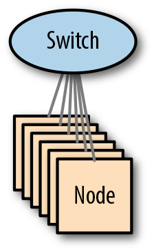
Figure 4-3. A single-switch architecture
From a performance perspective, this design presents very few challenges. Almost all modern switches are non-blocking (meaning that all ports can be utilized simultaneously at full load), so internal traffic from shuffles and replication should be handled effortlessly.
However, although simple and performant, this network architecture suffers from an inherent lack of scalability—once a switch runs out of ports, a cluster can’t grow further. Since switch ports are often used for upstream connectivity as well as local servers, small clusters with high ingest requirements may have their growth restricted further.
Another downside of this architecture is that the switch is a SPOF—if it fails, the cluster will fail right along with it. Not all clusters need to be always available, but for those that do, the only resolution is to build a resilient network using multiple switches.
Implementation
With a single-switch architecture, because of the inherent simplicity of the design, there is very little choice in the implementation. The switch will host a single Layer 2 broadcast domain within a physical LAN or a single virtual LAN (VLAN), and all hosts will be in the same Layer 3 subnet.
Medium Cluster Architectures
When building clusters that will span multiple racks, we highly recommend the architectures described in “Large Cluster Architectures”, since they provide the highest levels of scalability and performance. However, since not all clusters need such high capabilities, more modest clusters may be able to use one of the alternative architectures described in this section.
Stacked networks
Some network vendors provide switches that can be stacked—connected together with high-bandwidth, proprietary cables, making them function as a single switch. This provides an inexpensive, low-complexity option for expanding beyond a single switch. Figure 4-5 shows an example of a stacked network.
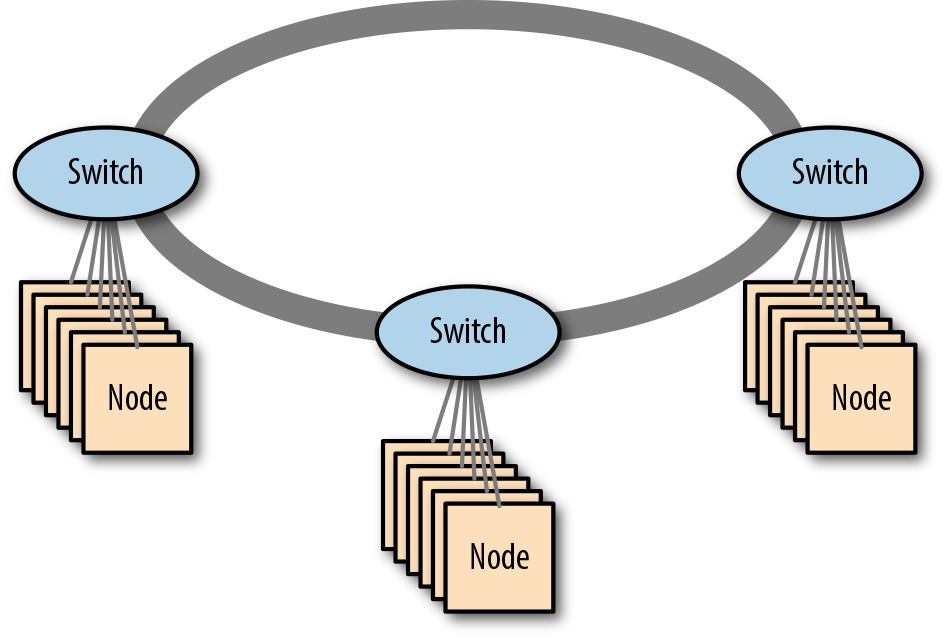
Figure 4-5. A stacked network of three switches
Although stacking switches may sound similar to using a highly available switch pair (which can also function as a single logical switch), they are in fact quite different. Stackable switches use their proprietary interconnects to carry high volumes of user data, whereas a high-availability (HA) switch pair only uses the interconnect for managing the switch state. Stacking isn’t limited to a pair of switches, either; many implementations can interconnect up to seven switches in a single ring (though as we’ll see, this has a large impact on oversubscription, severely affecting network performance).
Resiliency
Stackable switches connect using a bidirectional ring topology. Therefore, each participant always has two connections: clockwise and counterclockwise. This gives the design resiliency against ring link failure—if the clockwise link fails, traffic can flow instead via the counterclockwise link, though the overall network bandwidth might be reduced.
In the event of a switch failure in the ring, the other switches will continue to function, taking over leadership of the ring if needed (since one participant is the master). Any devices connected only to a single ring switch will lose network service.
Some stackable switches support Multi-Chassis Link Aggregation (see “Making Cluster Networks Resilient” on page 115). This allows devices to continue to receive network service even if one of the switches in the ring fails, as long as the devices connect to a pair of the switches in the stack. This configuration enables resilient stacked networks to be created (see Figure 4-6 for an example).
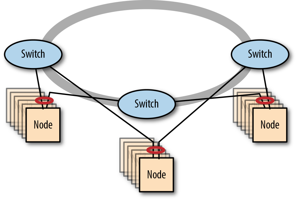
Figure 4-6. A resilient stacked network of three switches
In normal operations, the bidirectional nature of the ring connections means there are two independent rings. During link or switch failure, the remaining switches detect the failure and cap the ends, resulting in a horseshoe-shaped, unidirectional loop.
Performance
The stacking interconnects provide very high bandwidth between the switches, but each link still provides less bandwidth than the sum of the ports, necessarily resulting in network oversubscription.
With only two switches in a ring, there are two possible routes to a target switch—clockwise and counterclockwise. In each direction, the target switch is directly connected. With three switches in a ring, the topology means that there are still only two possible directions, but now a target switch will only be directly connected in one direction. In the other direction, an intermediate switch is between the source and the target.
The need for traffic to traverse intermediate switches means that oversubscription increases as we add switches to the ring. Under normal circumstances, every switch in the ring has a choice of sending traffic clockwise or counterclockwise, and this can also affect network performance.
Determining oversubscription in stacked networks
Within a stacked network, there are now two potential paths between a source and destination device, which makes oversubscription more complex to determine, but conceptually the process is unchanged.
In this first scenario, we look at oversubscription between a pair of stacked switches, each of which has 48 10 GbE ports and bidirectional stacking links operating at 120 Gb/s (the flow diagram can be seen in Figure 4-7). Each switch is directly connected to the other by two paths, giving a total outbound flow capacity of 240 Gb/s. Since there is a potential 480 Gb/s inbound from the ports, we see an oversubscription ratio of 480:240, or 2:1.
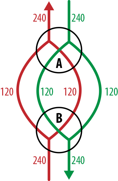
Figure 4-7. Network flows between a pair of stacked switches
With three switches in the ring, each switch is still directly connected to every other, but the 240 Gb/s outbound bandwidth is now shared between the two neighbors. Figure 4-8 shows the network flows that occur if we assume that traffic is perfectly balanced and the switches make perfect decisions about path selection (ensuring no traffic gets sent via an intermediate switch). In that scenario, each neighbor gets sent 120 Gb/s and the total outbound is 240 Gb/s, making the oversubscription ratio 2:1.
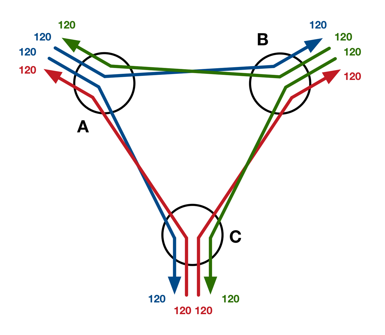
Figure 4-8. Best-case network flows between three stacked switches
If somehow the stacked switches were to make the worst possible path selections (sending all traffic via the longer path, as shown in Figure 4-9), the effective bandwidth would be reduced because each outbound link would now carry two flows instead of one. This increased contention would reduce the bandwidth available per flow to only 60 Gb/s, making the oversubscription ratio 480:120, or 4:1.
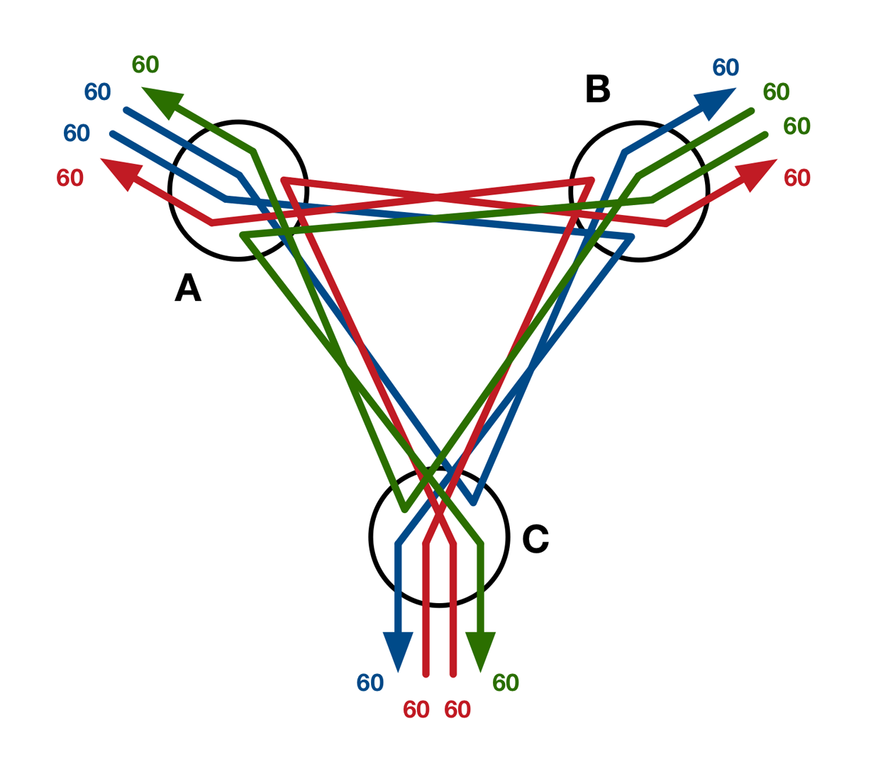
Figure 4-9. Worst-case network flows between three stacked switches
While this is a pathological example, it nevertheless demonstrates clearly the idea of a load-dependent oversubscription ratio. A real-world three-switch stack would almost certainly perform far closer to the best case than the worst, and in any case, even a 4:1 oversubscription ratio is still a reasonable proposition for a Hadoop cluster.
With only two switches in the stack, the traffic on the interconnection links was always direct. With three switches, the traffic is still mostly direct, with the possibility of some indirect traffic under high load.
When the ring has four switches or more, indirect traffic becomes completely unavoidable, even under perfect conditions. As switches are added to a stack, indirect traffic starts to dominate the workload, making oversubscription too problematic. Alternative architectures become more appropriate.
Stacked network cabling considerations
The proprietary stacking cables used to make the ring are very short—typically only a meter or so—and are designed for stacking switches in a literal, physical sense. It is possible for stacking switches to be placed in adjacent racks, but it’s generally best to avoid this, since not all racks allow cabling to pass between them.
One way around the ring cabling length restriction is to place the switch stack entirely in a single rack and use longer cables between the switches and servers. This has the disadvantage, though, of connecting all of the switches to a single power distribution unit (PDU), and is therefore subject to a single point of failure. If you need to place racks in different aisles due to space constraints, stacking isn’t for you.
Implementation
With a stacked-switch architecture, there are two implementation options to consider—deploying a subnet per switch or deploying a single subnet across the entire ring.
Deploying a subnet per switch is most appropriate for when servers connect to a single switch only. This keeps broadcast traffic local to each switch in the ring. In scenarios where servers connect to multiple stack switches using MC-LAG, deploying a single subnet across the entire ring is more appropriate.
In either scenario, a physical LAN or single VLAN per subnet is appropriate.
Fat-tree networks
Networks such as the fat-tree network are built by connecting multiple switches in a hierarchical structure. A single-core switch connects through layers of aggregation switches to access switches, which connect to servers.
The architecture is known as a fat tree because the links nearest the core switch are higher bandwidth, and thus the tree gets “fatter” as you get closer to the root. Figure 4-10 shows an example of a fat-tree network.
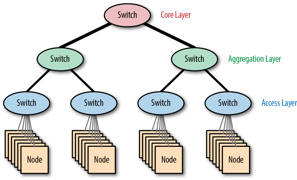
Figure 4-10. The fat-tree network architecture
Since many small clusters start by using a single switch, a fat-tree network can be seen as a natural upgrade path when considering network expansion. Simply duplicate the original single-switch design, add a core switch, and connect everything up.
Scalability
The performance of a fat-tree network can be determined by looking at the degree of network oversubscription. Consider the example in Figure 4-11.
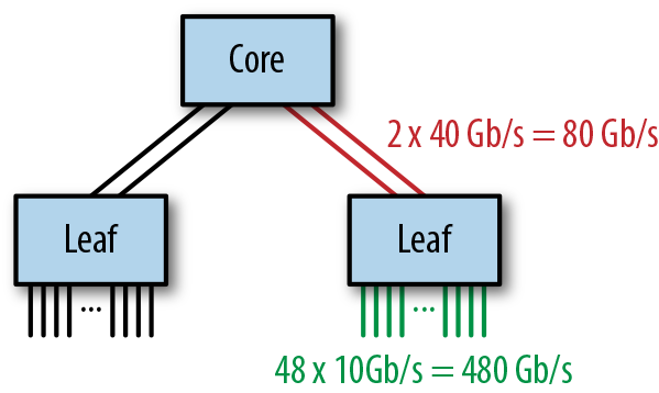
Figure 4-11. An example fat-tree network
The access switches each have 48 10 GbE ports connected to servers and 2 40 GbE ports connecting to the core switch, giving an oversubscription ratio of 480:80, or 6:1, which is considerably higher than recommended for Hadoop workloads. This can be improved by either reducing the number of servers per access switch or increasing the bandwidth between the access switches and the core switch using link aggregation.
This architecture scales out by adding access switches—each additional switch increases the total number of ports by 48. This can be repeated until the core switch port capacity is reached, at which point greater scale can only be achieved by using a larger core switch or a different architecture.
Resiliency
When implemented without redundant switches, the reliability of this architecture is limited due to the many SPOFs. The loss of an access switch would affect a significant portion of the cluster, and the loss of the core switch would be catastrophic.
Removing the SPOFs by replacing single switches with switch pairs greatly improves the resiliency. Figure 4-12 shows a fat-tree network built with multichassis link aggregation.
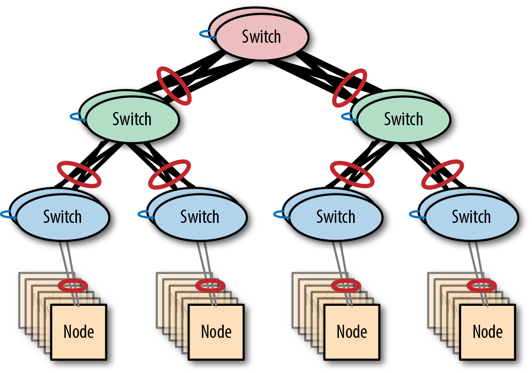
Figure 4-12. A resilient fat-tree network
Implementation
A hierarchical network can either be built using a single subnet across the entire tree or using a subnet per switch. The first option is easiest to implement, but it means that broadcast traffic will traverse links beyond the access layer. The second option scales better but is more complex to implement, requiring network administrators to manage routing—a process that can be error-prone.
Large Cluster Architectures
All of the architectures discussed so far have been limited in terms of either scale or scalability: single switches quickly run out of ports, stacked networks are limited to a few switches per stack at most, and fat-tree networks can only scale out while the core switch has enough ports.
This section discusses network designs that can support larger and/or more scalable clusters.
Modular switches
In general, there are only two ways to scale a network: scaling up using larger switches or scaling out using more switches. Both the fat-tree and the stacked network architectures scale out by adding switches. Prior to modular switches, scaling a switch vertically simply meant replacing it with a larger variant with a higher port capacity—a disruptive and costly option.
Modular switches introduced the idea of an expandable chassis that can be populated with multiple switch modules. Since a modular switch can function when only partially populated with modules, network capacity can be added by installing additional modules, so long as the chassis has space.
In many ways, a modular switch can be thought of as a scaled-up version of a single switch; thus it can be used in a variety of architectures. For example, a modular switch is well suited for use as the core switch of a fat tree or as the central switch in a single-switch architecture. The latter case is known as an end-of-row architecture, since the modular switch is literally deployed at the physical end of a datacenter row, connected to servers from the many racks in the row.
Modular switches, such as Cisco 7000, are often deployed in pairs in order to ensure resiliency in the architecture they are used in.
Spine-leaf networks
For true cluster-level scalability, a network architecture that can grow beyond the confines of any single switch—even a monstrous modular behemoth—is essential.
When we looked at the architecture of a fat-tree network, we saw that the scalability was ultimately limited by the capacity of the core switch at the root of the tree. As long as the oversubscription at the leaf and intermediate switches is maintained at a reasonable level, we can keep scaling out the fat tree by adding additional switches until the core switch has no capacity left.
This limit can be raised by scaling up the core switch to a larger model (or adding a module to a modular switch), but Figure 4-13 shows an interesting alternative approach, which is to just add another root switch.
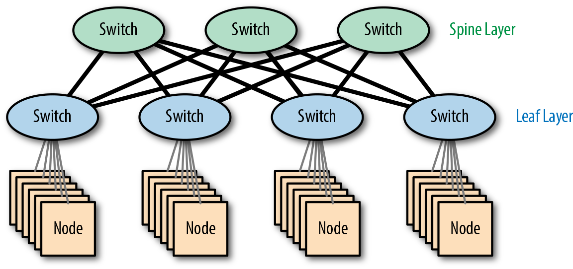
Figure 4-13. A spine-leaf network
Since there isn’t a single root switch, this isn’t a hierarchical network. In topology terms, the design is known as a partial mesh—partial since leaf switches only connect to core switches and core switches only connect to leaf switches.
The core switches function as the backbone of the network and are termed spine switches, giving us the name spine leaf.
Scalability
The most important benefit of the spine-leaf architecture is linear scalability: if more capacity is required, we can grow the network by adding spine and leaf switches, scaling out rather than scaling up. This finally allows the network to scale horizontally, just like the cluster software it supports.
Since every spine switch connects to every leaf switch, the scalability limit is determined by the number of ports available at a single spine switch. If a spine switch has 32 ports, each at 40 Gb/s, and each leaf switch needs 160 Gb/s in order to maintain a reasonable oversubscription ratio, we can have at most 8 leaf switches.
Resilient spine-leaf networks
When making networks resilient, the primary technique has been to use redundant switches and MC-LAG. Until now, this has been required for all switches in an architecture, since any switch without a redundant partner would become a SPOF.
With the spine-leaf architecture, this is no longer the case. By definition, a spine-leaf network already has multiple spine switches, so the spine layer is already resilient by design. The leaf layer can be made resilient by replacing each leaf switch with a switch pair, as shown in Figure 4-14. Both of these switches then connect to the spine layer for data, as well as each other for state management.
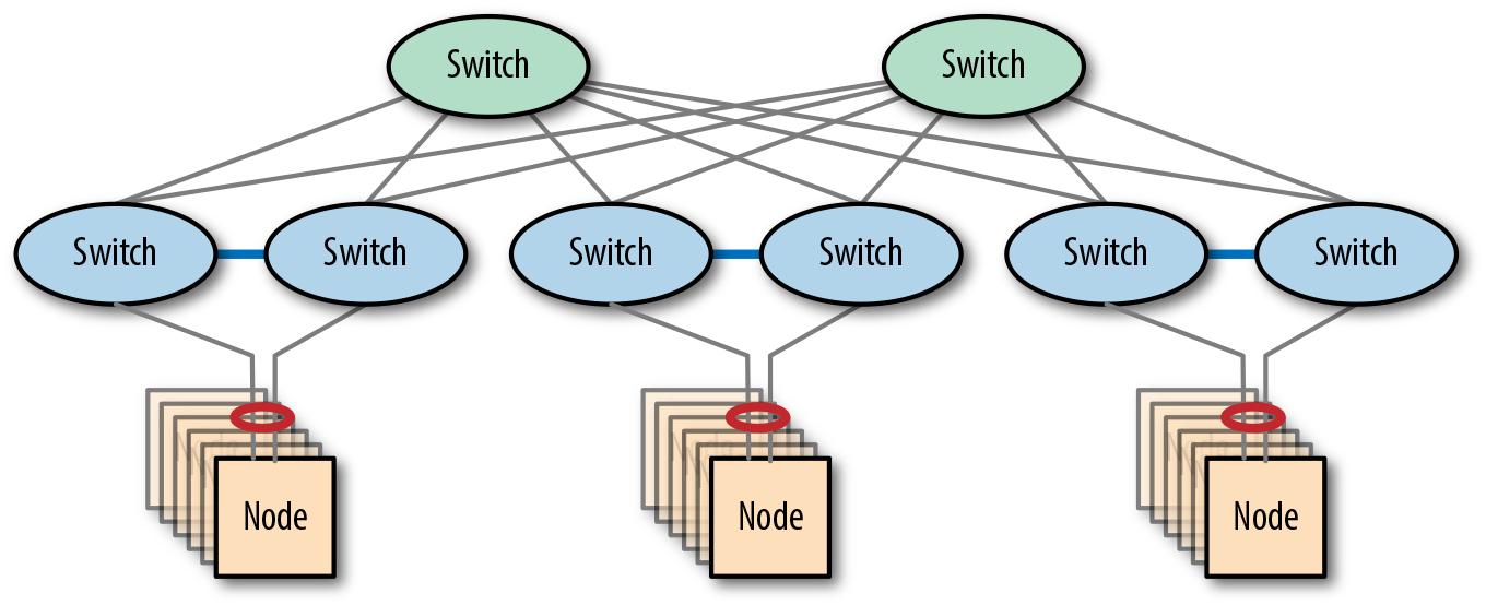
Figure 4-14. A resilient spine-leaf network
Implementation
Since a spine-leaf architecture contains loops, the implementation option of putting all devices into the same broadcast domain is no longer valid. Broadcast frames would simply flow around the loops, creating a broadcast storm, at least until the Spanning Tree Protocol (STP) disabled some links.
The option to have a subnet (broadcast domain) per leaf switch remains, and is a scalable solution since broadcast traffic would then be constrained to the leaf switches. This implementation option again requires network administrators to manage routing, however, which can be error-prone.
An interesting alternative implementation option is to deploy a spine-leaf network using a network fabric rather than using routing at the IP layer.
Network Integration
A cluster is a significant investment that requires extensive networking, so it makes sense to consider the architecture of a cluster network in isolation. However, once the network architecture of the cluster is settled, the next task is to define how that cluster will connect to the world.
There are a number of possibilities for integrating a cluster into a wider network. This section describes the options available and outlines their pros and cons.
Reusing an Existing Network
The first approach—only really possible for small clusters—is to add the cluster to a preexisting subnet. This is the simplest approach, since it requires the least change to existing infrastructure. Figure 4-15 shows how, at a logical level, this integration path is trivial, since we’re only adding new cluster servers.
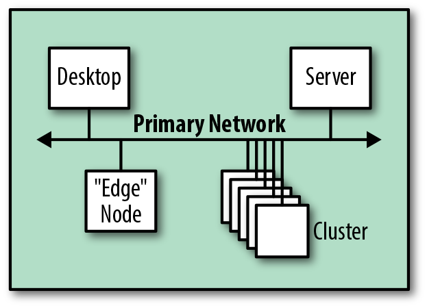
Figure 4-15. Logical view of an integration with an existing network
From a physical perspective, this could be implemented by reusing existing switches, but unless all nodes would be located on the same switch, this could easily lead to oversubscription issues. Many networks are designed more for access than throughput.
A better implementation plan is to introduce additional switches that are dedicated to the cluster, as shown in Figure 4-16. This is better in terms of isolation and performance, since internal cluster traffic can remain on the switch rather than transiting via an existing network.

Figure 4-16. Physical view of possible integrations with an existing network
Creating an Additional Network
The alternative approach is to create additional subnets to host the new cluster. This requires that existing network infrastructure be modified, in terms of both physical connectivity and configuration. Figure 4-17 shows how, from a logical perspective, the architecture is still straightforward—we add the cluster subnet and connect to the main network.
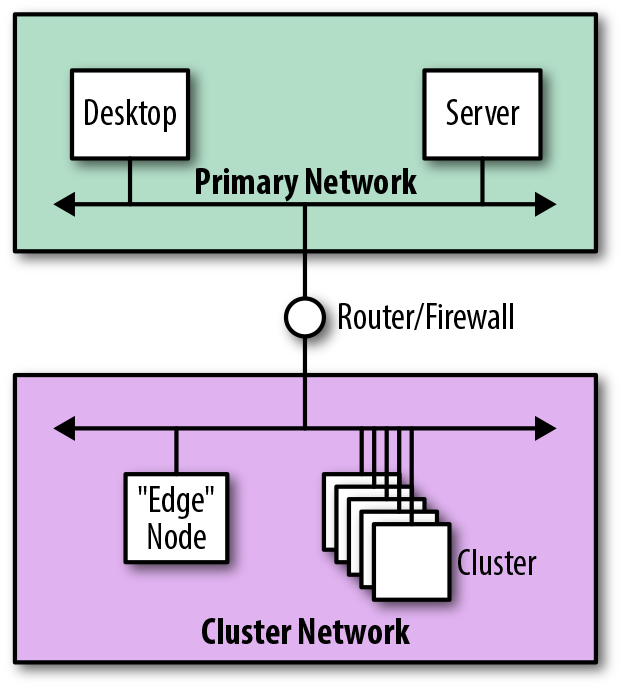
Figure 4-17. Logical view of integration using an additional network
From a security perspective, this approach is preferable since the additional isolation keeps broadcast traffic away from the main network. By replacing the router with a firewall, we can entirely segregate the cluster network and tightly control which servers and services are visible from the main network.
Edge-connected networks
Edge nodes are typically cluster servers that are put in place to provide access to cluster services, offering SSH access, hosting web UIs, or providing JDBC endpoints to upstream middleware systems. They form the boundary, or edge, of the software services provided by a cluster.
Figure 4-18 shows how, rather than connecting a cluster through a router or firewall, the edge nodes could provide external network connectivity to the cluster.
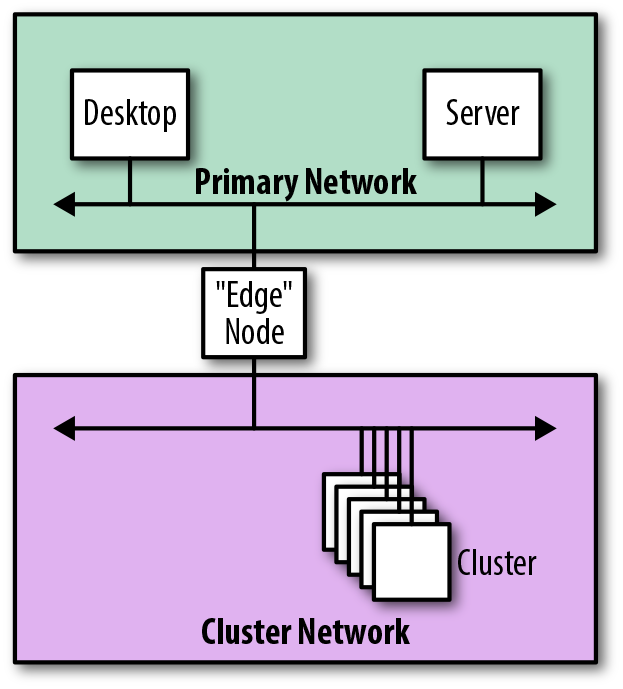
Figure 4-18. Logical view of integration using an edge node
When connected in this manner, the edge nodes literally form the physical edges of the cluster, acting as the gateway through which all communication is performed. The downside of this approach is that the edge nodes are multihomed, which, in general, isn’t recommended.
Network Design Considerations
This section outlines network design recommendations and considerations based on reference architectures, known best practices, and the experiences of the authors. The intent is to provide some implementation guidelines to help ensure a successful deployment.
Layer 1 Recommendations
The following recommendations concern aspects of Layer 1, known as the physical layer. This is where the rubber meets the road, bridging the gap between the logical world of software and the physical world of electronics and transmission systems.
- Use dedicated switches
-
Although it may be possible to use existing network infrastructure for a new cluster, we recommend deploying dedicated switches and uplinks for Hadoop where possible. This has several benefits, including isolation and security, cluster growth capacity, and stronger guarantees that traffic from Hadoop and Spark won’t saturate existing network links.
- Consider a cluster as an appliance
-
This is related to the previous point, but it is helpful to think of a cluster as a whole, rather than as a collection of servers to be added to your network.
When organizations purchase a cluster as an appliance, installation becomes a relatively straightforward matter of supplying space, network connectivity, cooling, and power—the internal connectivity usually isn’t a concern. Architecting and building your own cluster means you necessarily need to be concerned with internal details, but the appliance mindset—thinking of the cluster as a single thing—is still appropriate.
- Manage oversubscription
-
The performance of any cluster network is entirely driven by the level of oversubscription at the switches. Cluster software, such as Hadoop and Spark, can drive a network to capacity, so the network should be designed to minimize oversubscription. Cluster software performs best when oversubscription is kept to around 3:1 or better.
- Consider InfiniBand carefully
-
Hadoop clusters can be deployed using InfiniBand (IB) as the Layer 1 technology, but this is uncommon outside of Hadoop appliances.
At the time of this writing, InfiniBand isn’t supported natively by services such as Hadoop and Spark. Features such as remote direct memory access (RDMA) are thus left unused, making the use of IP over InfiniBand (IPoIB) essential. As a consequence, the performance of InfiniBand is significantly reduced, making the higher speeds of InfiniBand less relevant.
InfiniBand also introduces a secondary network interface to cluster servers, making them multihomed. As discussed in “Layer 3 Recommendations”, this should be avoided. Finally, the relative scarcity of InfiniBand skills in the market and the cost in comparison to Ethernet make the technology more difficult to adopt and maintain.
- Use high-speed cables
-
Clusters are commonly cabled using copper cables. These are available in a number of standards, known as categories, which specify the maximum cable length and maximum speed at which a cable can be used.
Since the cost increase between cable types is negligible when compared to servers and switches, it makes sense to choose the highest-rated cable possible. At the time of this writing, the recommendation is to use Category 7a cable, which offers speeds of up to 40 Gb/s with a maximum distance of 100 meters (for solid core cables; 55 meters for stranded).
Fiber optic cables offer superior performance in terms of bandwidth and distance compared to copper, but at increased cost. They can be used to cable servers, but they are more often used for the longer-distance links that connect switches in different racks. At this time, the recommendation is to use OM3 optical cabling or better, which allows speeds up to 100 Gb/s.
- Use high-speed networking
-
The days of connecting cluster servers at 1 Gb/s are long gone. Nowadays, almost all clusters should connect servers using 10 Gb/s or better. For larger clusters that use multiple switches, 40 Gb/s should be considered the minimum speed for the links that interconnect switches. Even with 40 Gb/s speeds, link aggregation is likely to be required to maintain an acceptable degree of oversubscription.
- Consider hardware placement
-
We recommend racking servers in predictable locations, such as always placing master nodes at the top of the rack or racking servers in ascending name/IP order. This strategy can help to reduce the likelihood that a server is misidentified during cluster maintenance activities. Better yet, use labels and keep documentation up to date.
Ensure that racks are colocated when considering stacked networks, since the stacking cables are short. Remember that server network cables may need to be routed between racks in this case.
Ensure that racks are located no more than 100 meters apart when deploying optical cabling.
- Don’t connect clusters to the internet
-
Use cases that require a cluster to be directly addressable on the public internet are rare. Since they often contain valuable, sensitive information, most clusters should be deployed on secured internal networks, away from prying eyes. Good information security policy says to minimize the attack surface of any system, and clusters such as Hadoop are no exception.
When absolutely required, internet-facing clusters should be deployed using firewalls and secured using Kerberos, Transport Layer Security (TLS), and encryption.
Layer 2 Recommendations
The following recommendations concern aspects of Layer 2, known as the data link layer, which is responsible for sending and receiving frames between devices on a local network. Each frame includes the physical hardware addresses of the source and destination, along with a few other fields.
- Avoid oversized layer 2 networks
-
Although IP addresses are entirely determined by the network configuration, MAC addresses are effectively random (except for the vendor prefix). In order to determine the MAC address associated with an IP address, the Address Resolution Protocol (ARP) is used, performing address discovery by broadcasting an address request to all servers in the same broadcast domain.
Using broadcasts for address discovery means that Layer 2 networks have a scalability limitation. A practical general rule is that a single broadcast domain shouldn’t host more than approximately 500 servers.
- Minimize VLAN usage
-
Virtual LANs were originally designed to make the link deactivation performed by the Spanning Tree Protocol less expensive, by allowing switches and links to simultaneously carry multiple independent LANs, each of which has a unique spanning tree. The intention was to reduce the impact of link deactivation by allowing a physical link to be deactivated in one VLAN while still remaining active in others.
In practice, VLANs are almost never used solely to limit the impact of STP; the isolating nature of VLANs is often much more useful in managing service visibility, increasing security by restricting broadcast scope.
VLANs are not required for cluster networks—physical LANs are perfectly sufficient, since in most cases a cluster has dedicated switches anyway. If VLANs are deployed, their use should be minimized to, at most, a single VLAN per cluster or a single VLAN per rack for clusters built using Layer 3 routing. Use of multiple VLANs per server is multihoming, which is generally not recommended.
- Consider jumbo frames
-
Networks can be configured to send larger frames (known as jumbo frames) by increasing the maximum transmission unit (MTU) from 1,500 to 9,000 bytes. This increases the efficiency of large transfers, since far fewer frames are needed to send the same data. Cluster workloads such as Hadoop and Spark are heavily dependent on large transfers, so the efficiencies offered by jumbo frames make them an obvious design choice where they are supported.
In practice, jumbo frames can be problematic because they need to be supported by all participating switches and servers (including external services, such as Active Directory). Otherwise, fragmentation can cause reliability issues.
- Consider network resiliency
-
As mentioned previously, one approach to making a network resilient against failure is to use Multi-Chassis Link Aggregation. This builds on the capabilities of link aggregation (LAG) by allowing servers to connect to a pair of switches at the same time, using only a single logical connection. That way, if one of the links or switches were to fail, the network would continue to function.
In addition to their upstream connections, the redundant switches in the pair need to be directly connected to each other. These links are proprietary (using vendor-specific naming and implementations), meaning that switches from different vendors (even different models from the same vendor) are incompatible. The proprietary links vary as to whether they carry cluster traffic in addition to the required switch control data.
Enterprise-class deployments will almost always have managed switches capable of using LACP, so it makes good sense to use this capability wherever possible. LACP automatically negotiates the aggregation settings between the server and a switch, making this the recommended approach for most deployments.
Layer 3 Recommendations
The following recommendations concern aspects of Layer 3, known as the network layer. This layer interconnects multiple Layer 2 networks together by adding logical addressing and routing capabilities.
- Use dedicated subnets
-
We recommend isolating network traffic to at least a dedicated subnet (and hence broadcast domain) per cluster. This is useful for managing broadcast traffic propagation and can also assist with cluster security (through network segmentation and use of firewalls). A subnet range of size /22 is generally sufficient for this purpose since it provides 1,024 addresses—most clusters are smaller than this.
For larger clusters not using fabric-based switching, a dedicated subnet per rack will allow the switches to route traffic at Layer 3 instead of just switching frames. This means that the cluster switches can be interconnected with multiple links without the risk of issues caused by STP. A subnet range of size /26 is sufficient, since it provides 64 addresses per rack—most racks will have fewer servers than this.
Each cluster should be assigned a unique subnet within your overall network allocation. This ensures that all pairs of servers can communicate, in the event that data needs to be copied between clusters.
- Allocate IP addresses statically
-
We strongly recommend allocating IP addresses statically to cluster servers during the OS build and configuration phase, rather than dynamically using DHCP on every boot. Most cluster services expect IP addresses to remain static over time. Additionally, services such as Spark and Hadoop are written in Java, where the default behavior is to cache DNS entries forever when a security manager is installed.
If DHCP is used, ensure that the IP address allocation is stable over time by using a fixed mapping from MAC addresses to IP addresses—that way, whenever the server boots, it always receives the same IP address, making the address effectively static.
- Use private IP address ranges
-
In most cases, internal networks within an organization should be configured to use IP addresses from the private IP address ranges. These ranges are specially designated for use by internal networks—switches on the internet will drop any packets to or from private addresses.
The multiple private IP ranges available can be divided into subnets. Table 4-2 shows the ranges.
Table 4-2. Private IP address ranges IP address range Number of IP addresses Description 10.0.0.0–10.255.255.255
16,777,216
Single Class A network
172.16.0.0–172.31.255.255
1,048,576
16 contiguous Class B networks
192.168.0.0–192.168.255.255
65,536
256 contiguous Class C networks
For clusters like Hadoop, we strongly recommend use of a private network. When deploying a cluster, however, take care to ensure that a private network range is only used once within an organization—two clusters that clash in terms of IP addresses won’t be able to communicate.
- Prefer DNS over /etc/hosts
-
Cluster servers are almost always accessed via hostnames rather than IP addresses. Apart from being easier to remember, hostnames are specifically required when using security technologies such as TLS and Kerberos. Resolving a hostname into an IP address is done via either the Domain Name System (DNS) or the local configuration file /etc/hosts.
The local configuration file (which allows for entries to be statically defined) does have some advantages over DNS:
- Precedence
Local entries take precedence over DNS, allowing administrators to override specific entries.
- Availability
As a network service, DNS is subject to service and network outages, but /etc/hosts is always available.
- Performance
DNS lookups require a minimum of a network round trip, but lookups via the the local file are instantaneous.
Even with these advantages, we still strongly recommend using DNS. Changes made in DNS are made once and are immediately available. Since /etc/hosts is a local file that exists on all devices, any changes need to be made to all copies. At the very least, this will require deployment automation to ensure correctness, but if the cluster uses Kerberos changes will even need to be made on clients. At that point, DNS becomes a far better option.
The availability and performance concerns of DNS lookups can be mitigated by using services such as the Name Service Caching Daemon (NSCD).
Finally, regardless of any other considerations, all clusters will interact with external systems. DNS is therefore essential, both for inbound and outbound traffic.
- Provide forward and reverse DNS entries
-
In addition to using DNS for forward lookups that transform a hostname into an IP address, reverse DNS entries that allow lookups to transform an IP address into a hostname are also required.
In particular, reverse DNS entries are essential for Kerberos, which uses them to verify the identity of the server to which a client is connecting.
- Never resolve a hostname to 127.0.0.1
-
It is essential to ensure that every cluster server resolves its own hostname to a routable IP address and never to the localhost IP address 127.0.0.1—a common misconfiguration of the local /etc/hosts file.
This is an issue because many cluster services pass their IP address to remote systems as part of normal RPC interactions. If the localhost address is passed, the remote system will then incorrectly attempt to connect to itself later on.
- Avoid IPv6
-
There are two types of IP address in use today: IPv4 and IPv6. IPv4 was designed back in the 1970s, with addresses taking up 4 bytes. At that time, 4,294,967,296 addresses was considered to be enough for the foreseeable future, but rapid growth of the internet throughout the 1990s led to the development of IPv6, which increased the size of addresses to 16 bytes.
Adoption of IPv6 is still low—a report from 2014 indicates that only 3% of Google users use the site via IPv6. This is partly due to the amount of infrastructural change required and the fact that workarounds, such as Network Address Translation (NAT) and proxies, work well enough in many cases.
At the time of this writing, the authors have yet to see any customer network—cluster or otherwise—running IPv6. The private network ranges provide well over 16 million addresses, so IPv6 solves a problem that doesn’t exist within the enterprise space.
If IPv6 becomes more widely adopted in the consumer internet, there may be a drive to standardize enterprise networking to use the same stack. When that happens, data platforms will take more notice of IPv6 and will be tested more regularly against it. For now, it makes more sense to avoid IPv6 entirely.
- Avoid multihoming
-
Multihoming is the practice of connecting a server to multiple networks, generally with the intention of making some or all network services accessible from multiple subnets.
When multihoming is implemented using a hostname-per-interface approach, a single DNS server can be used to store the multiple hostname entries in a single place. However, this approach doesn’t work well with Hadoop when secured using Kerberos, since services can only be configured to use a single service principal name (SPN), and an SPN includes the fully qualified hostname of a service.
When multihoming is implemented using the hostname-per-server approach, a single DNS server is no longer sufficient. The IP address required by a client now depends on which network the client is located on. Solving this problem adds significant complexity to network configuration, usually involving a combination of both DNS and /etc/hosts. This approach also adds complexity when it comes to Kerberos security, since it is essential that forward and reverse DNS lookups match exactly in all access scenarios.
Multihoming is most frequently seen in edge nodes, as described in “Edge-connected networks”, where edge services listen on multiple interfaces for incoming requests. Multihomed cluster nodes should be avoided where possible, for the following reasons:
Summary
In this chapter we discussed how cluster services such as Spark and HDFS use networking, how they demand the highest levels of performance and availability, and ultimately how those requirements drive the network architecture and integration patterns needed.
Equipped with this knowledge, network and system architects should be in a good position to ensure that the network design is robust enough to support a cluster today, and flexible enough to continue to do so as a cluster grows.
Get Architecting Modern Data Platforms now with the O’Reilly learning platform.
O’Reilly members experience books, live events, courses curated by job role, and more from O’Reilly and nearly 200 top publishers.

