April 2020
Intermediate to advanced
795 pages
17h 43m
English
There are a variety of ways to connect components when you build a circuit. The most common practice, especially during the prototyping phase, is to use a solderless breadboard. As you build your circuit, you will need to power it, and with power comes the need to manage power fluctuations. This appendix explains the basics of breadboarding and offers some tips on working with power supplies.
A breadboard enables you to prototype circuits quickly, without having to solder the connections. Figure C-1 shows an example of a breadboard.
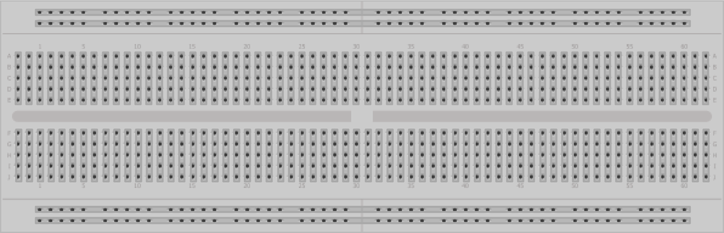
Breadboards come in various sizes and configurations. The simplest kind is just a grid of holes in a plastic block. Inside are strips of metal that provide electrical connections between holes in the shorter rows. Pushing the legs of two different components into the same row joins them together electrically. A deep channel running down the middle indicates that there is a break in connections there, meaning you can push a chip in with the legs at either side of the channel without connecting them together.
Some breadboards have two strips of holes running along the long edges of the board that are separated from the main grid. These have strips running down the length of the board inside, and provide a way to connect a common voltage. They are usually in pairs ...
Read now
Unlock full access


