Chapter 3
Rotor in Vertical Flight: Blade Element Theory
3.1 Basic Method
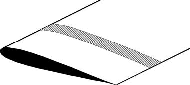
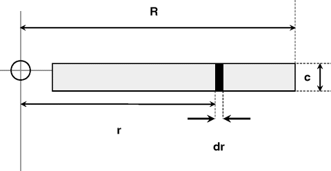
Blade element theory is basically the application of the standard process of aerofoil theory to the rotating blade. A typical aerodynamic strip is shown in Figure 3.1 and the appropriate notation for a typical strip is shown in Figure 3.2. Although in reality flexible, a rotor blade is assumed throughout to be rigid, the justification for this lying in the fact that at normal rotation speeds the outward centrifugal force is the largest force acting on a blade and, in effect, is sufficient to hold the blade in rigid form. In vertical flight, including hover, the main complication is the need to integrate the elementary forces along the blade span. Offsetting this, useful simplification occurs because the blade incidence and induced flow angles are normally small enough to allow small-angle approximations to be made.
Figure 3.1 General strip used in blade aerodynamic calculations

Figure 3.2 Blade strip coordinates

Figure 3.3 is a plan view of the rotor disc, seen from above. Blade rotation is anticlockwise (the normal system in the UK and the USA) with angular velocity Ω. The blade radius is R, the tip speed therefore being ΩR, alternatively written as VT. An elementary blade section is taken at radius r

