April 2015
Beginner to intermediate
346 pages
6h 18m
English
In this chapter, you will learn how to control physical hardware via
BeagleBone Black’s general-purpose input/output (GPIO) pins. The Bone has 65 GPIO pins that are brought out on two 46-pin headers, called P8 and P9, as shown in Figure 3-1.

The purpose of this chapter is to give simple examples that show how to use various methods of output. Most solutions require a breadboard and some jumper wires.
All these examples assume that you know how to edit a file (Recipe 1.6) and run it, either within Cloud9 integrated development environment (IDE) or from the command line (Recipe 5.3).
You want to know how to flash the four LEDs that are next to the Ethernet port on the Bone.
Locate the four onboard LEDs shown in Figure 3-2. They are labeled USR0 through USR3, but we’ll refer to them as the USER LEDs.
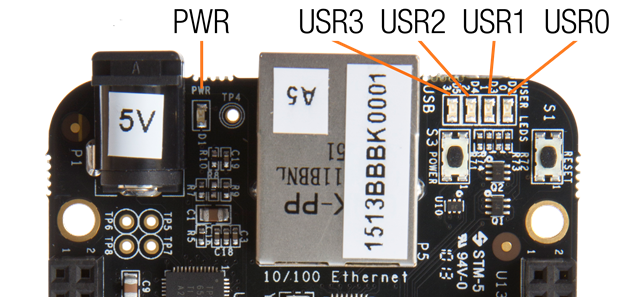
USER LEDsPlace the code shown in Example 3-1 in a file called internLED.js. You can do this using Cloud9 to edit files (as shown in Recipe 1.6) or with a more traditional editor (as shown in Recipe 5.9).
#!/usr/bin/env node var b = require('bonescript'); var LED = 'USR0'; ...Read now
Unlock full access


