12
H∞ Voltage-Current Control of a Neutral Leg
In Chapter 11, a voltage-current controller is designed with classical control techniques to control an independently-controlled neutral leg. In this chapter, the advanced H∞ control technique is applied to design a controller so that it leads to very small deviations of the neutral point from the mid-point of the DC link, in spite of possibly very large neutral currents.
12.1 Mathematical Modelling
The independently-controlled neutral leg shown in Figure 10.3 is re-drawn in Figure 12.1 for convenience. The objective of the neutral controller is to generate firing pulses to turn the switches S+ and S− ON or OFF, in a complementary way, so that the neutral point is very close to the mid-point of the DC link. This can be achieved by maintaining the inductor current iL equal to the neutral current iN so that no current flows through the capacitors. Thus, the capacitors maintain constant and equal voltages and, hence, the neutral point remains balanced. The mathematical model of the neutral leg is established in a slightly different way from that in Chapter 11, taking into account the resistance of the inductor and the mismatch of the capacitors.
Figure 12.1 Independently-controlled neutral leg under consideration
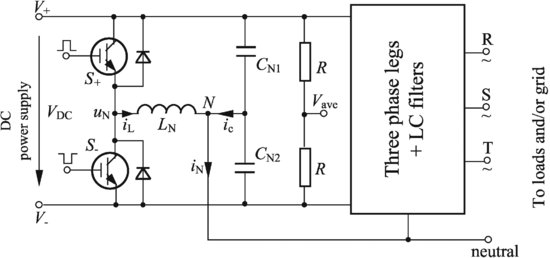
Assume that all voltages are measured with respect to the neutral point N. The DC-link voltage is
and the mid-point ...
Get Control of Power Inverters in Renewable Energy and Smart Grid Integration now with the O’Reilly learning platform.
O’Reilly members experience books, live events, courses curated by job role, and more from O’Reilly and nearly 200 top publishers.

