8
Design and Analysis of Composite Beams
The term beams is used here as a generic term referring to all one-dimensional parts that may be used in a structure. These include stiffeners, stringers, panel breakers, etc. There are many cross-sectional shapes that are used in practice. Of those, the ones used most frequently are (Figure 8.1) L or angle, C or channel, Z, T or blade, I, J and Hat or omega.
Figure 8.1 Typical beam cross-sections

8.1 Cross-Section Definition Based on Design Guidelines
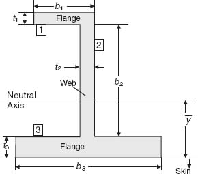
For a composite beam such as the one shown in Figure 8.2, each member may have a different layup. This would result in different stiffnesses and strengths for each of the flanges and web and would allow more efficient usage of composite materials through tailoring. Typically, the letter b with appropriate subscript is used to denote the longer dimension of each member and the letter t the shortest (the thickness).
Figure 8.2 J stiffener cross-section

As beams tend to be used in stability-critical situations, cross-sections with high moments of inertia are preferred. Besides the obvious implications for the beam geometry (high b2 value, e.g. in Figure 8.2), there are certain guidelines that relate to the layup, which, when implemented, also contribute to robust performance.
With reference ...
Get Design and Analysis of Composite Structures: With Applications to Aerospace Structures, 2nd Edition now with the O’Reilly learning platform.
O’Reilly members experience books, live events, courses curated by job role, and more from O’Reilly and nearly 200 top publishers.

