Appendix 2
Noise in a Balanced Amplifier
A2.1. Lossless directional coupler
The flow diagram including the noise sources for both amplifiers is shown in Figure A2.1. This figure suppose that both directional couplers are ideal and that the unused ports 3 and 4 are closed by perfectly matched loads. The noise generated by these matched loads is illustrated by the noise power waves bLN3 and bLN4.
Figure A2.1. Flow diagram of a balanced amplifier
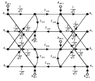
The balanced amplifier is the two-port network comprised between ports 1 and 2. As the graph does not have loops, it is easy to calculate the output waves at ports 1 and 2 through the superposition theorem.
If we do not take the noise sources into account:
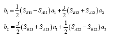
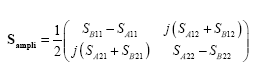
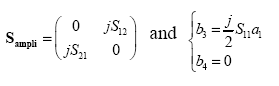
The balanced amplifier’s scattering matrix is expressed as:
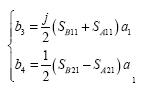
The output waves at the unused ports 3 and 4 are written as:
If the two simple amplifiers are identical SA = SB = S, the matrix can be simplified as:
So we observe that the resulting amplifier is matched within the meaning of travelling ...
Get Design of Microwave Active Devices now with the O’Reilly learning platform.
O’Reilly members experience books, live events, courses curated by job role, and more from O’Reilly and nearly 200 top publishers.

