7.1. Theoretical background
7.1.1. Transfer function and filter specifications for infinite impulse response (IIR) filters
The infinite impulse response (IIR) filters, also called recursive filters due to the implementation method, are defined by the finite difference equation below:

This equation results in the following rational transfer function in the z-domain:
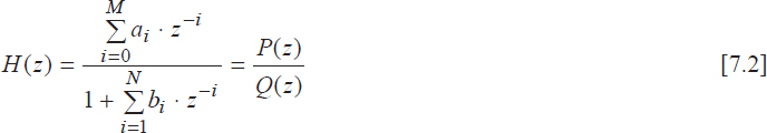
where at least one of the bi coefficients is non-zero and M < N.
The IIR filters are quite similar to the analog filters. Indeed, in both cases the filter specifications are defined in the form of margin constraints on its frequency response (magnitude, phase and group propagation time). An example is provided in the figure below for the transfer function magnitude of a lowpass analog (a) and IIR digital (b) filter.
δ0(Δ0) stands for the maximum accepted passband ripple, δb (Δb) is the minimum required stopband rejection (or attenuation), [ωp, ωb] ([Ωp, Ωb]) defines the transition band and ωc (Ωc) represents the cutoff frequency.
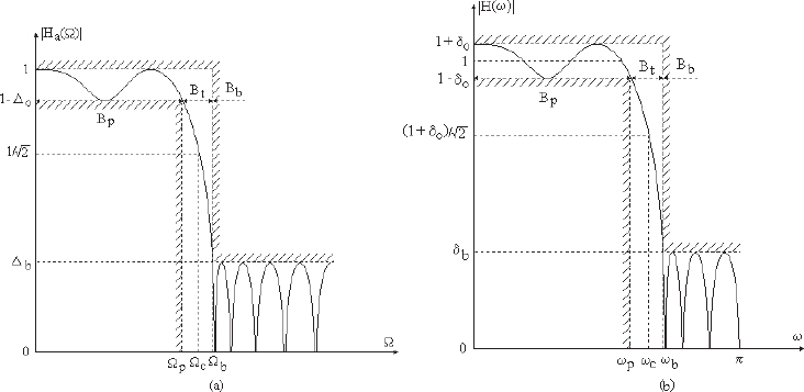
Figure 7.1. Filter specifications for the transfer function magnitude of an analog (a) and an IIR digital lowpass filter (b)
The specifications of the two types of filters are linked by the following ...
Get Digital Signal Processing Using Matlab now with the O’Reilly learning platform.
O’Reilly members experience books, live events, courses curated by job role, and more from O’Reilly and nearly 200 top publishers.

