Appendix E
F and G Matrix Calculations
The transition and the input matrix of the discretized state-space equations for the IPM-SM, must be calculated in the (d, q) reference frame, which turns with the rotor, following the rotor magnetic anisotropy, to allow to:
- filter measurements made in the (α, β) fixed frame: the two-phase currents and the position of the rotor, generally
- predict an initial state-space during the control computation.
These two matrices F and G (cf. equations (3.124)) are calculated, from the exponential function of the diagonalized evolution matrix D multiplied by the sampling period T (cf. equation (3.69)), from the input matrix B of the continuous-time state-space equations, and from the transfer matrix and its inverse, calculated in Appendix B and C respectively:
![]() (E.1)
(E.1)
In addition, the expression of D− 1 ⋅ (eD ⋅ T − I) ⋅ P− 1 ⋅ B, was already calculated in (3.72).
E.1 Transition Matrix Calculation
We will start by calculating eD ⋅ T ⋅ P− 1, by simply creating the product of the two matrices eD ⋅ T by P− 1, and then we will multiply the result by the matrix P on the left.
(E.2) 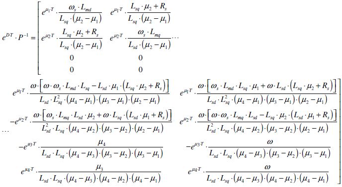
To reduce the first row of the produced matrix, we then use equations (3.42) and (3.44) and the reduced variable ζd1, defined in (3.49). A new relation is thus obtained:
(E.3)
To reduce ...
Get Direct Eigen Control for Induction Machines and Synchronous Motors now with the O’Reilly learning platform.
O’Reilly members experience books, live events, courses curated by job role, and more from O’Reilly and nearly 200 top publishers.

