Chapter 7
HSDPA Antenna Spacing Measurements
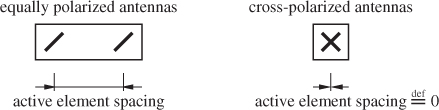
In cellular mobile radio communication, not only do users demand small mobile phones, but mobile operators also demand small Base station (NodeB) antennas. Unfortunately, the recently emerged trend towards more antennas at the transmit and receive side of a radio link (referred to as Multiple-Input Multiple-Output (MIMO)) considerably increases the width of NodeB antennas if multiple elements have to be placed immediately adjacent to each other. While several configurations are possible, for the case of two antennas, two setups are usually favored at a mobile phone operator's NodeB (see Figure 7.1).
Figure 7.1 Cross-polarized and equally polarized transmit antennas.
7.1 Problem Formulation
Given a specific transmitter and receiver position, we want to directly measure the mean closed-loop physical-layer Downlink (DL) throughput of 2 × 2 MIMO Universal Mobile Telecommunications System (UMTS) High-Speed Downlink Packet Access (HSDPA) for equally polarized transmit antennas at variable antenna spacings and for cross-polarized transmit antennas. We want to do so by employing realistic transmit antennas (see Figure 7.2), realistic receive antennas (see Figure 7.4), and transmitting standard-compliant HSDPA data frames [2] including the HSDPA pilot structure (see Chapter 5). In this experiment, we do not want to investigate multi-user and ...

