8Systematic Methods of Circuit Analysis
8.1 Node Voltage Analysis
8.1.1 Node Analysis for the Resistive Circuits
In Chapter 7 we discussed the basic circuit laws that impose constraints on voltages and currents in the circuit. To be more precise, the voltages and currents we referred to were the element voltages and element currents.
Using KCL, KVL, and Ohm’s law to solve for the element voltages and currents can be quite cumbersome, except for the very simple circuits.
In this section we present a systematic method of circuit analysis in which node voltages are the circuit variables to be found. As we shall see, choosing node voltages instead of the element voltages as circuit variables allows us to develop a systematic method of circuit analysis that is applicable to more complex circuits.
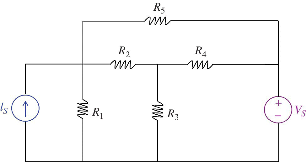
We will use the circuit shown in Figure 8.1 to define node voltages and explain the node voltage analysis method.

Figure 8.1 Node voltage analysis circuit.
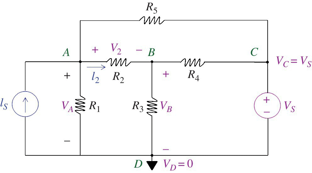
To define a set of node voltages we first select one node in the network to be a reference node – node D, shown in Figure 8.2. By definition, the node voltage at the reference node is equal to zero (Nilsson and Riedel, 2015, p. 93).

Figure 8.2 Node ...
Get Foundations of Electromagnetic Compatibility with Practical Applications now with the O’Reilly learning platform.
O’Reilly members experience books, live events, courses curated by job role, and more from O’Reilly and nearly 200 top publishers.

