Appendix Testbenches
A–1. Adder and Subtractor Testbench
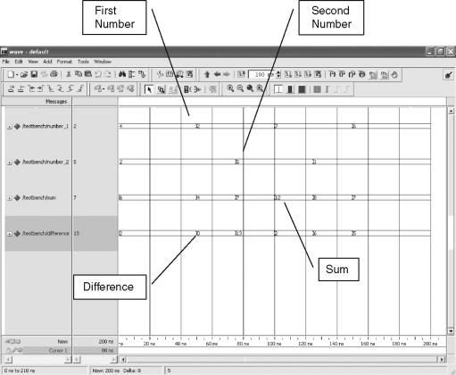
Use this testbench to verify the adder and subtractor design in Chapter 2. An example of the simulated output is shown in Figure A-1.
Figure A-1. Adder and Subtractor Simulation Outputs
(Material based on or adapted from figures and text owned by Xilinx, Inc., courtesy of Xilinx, Inc. Copyright © Xilinx 1995–2008 used in Xilinx ISE WebPack™ software version 10.1.)
Run the simulation for 200.00 nsec.
- Library IEEE;
- Use IEEE.std_logic_1164.All;
- Use IEEE.std_logic_unsigned.All;
- Entity testbench Is End testbench;
- Architecture tb_MathematicalOperators Of testbench Is
- Signal number_1 : std_logic_vector(3 ...
Get FPGAs 101 now with the O’Reilly learning platform.
O’Reilly members experience books, live events, courses curated by job role, and more from O’Reilly and nearly 200 top publishers.

