Chapter 4. gRPC: Under the Hood
As you have learned in previous chapters, gRPC applications communicate using RPC over the network. As a gRPC application developer, you don’t need to worry about the underlying details of how RPC is implemented, what message-encoding techniques are used, and how RPC works over the network. You use the service definition to generate either server- or client-side code for the language of your choice. All the low-level communication details are implemented in the generated code and you get some high-level abstractions to work with. However, when building complex gRPC-based systems and running them in production, it’s vital to know how gRPC works under the hood.
In this chapter, we’ll explore how the gRPC communication flow is implemented, what encoding techniques are used, how gRPC uses the underlying network communication techniques, and so on. We’ll walk you through the message flow where the client invokes a given RPC, then discuss how it gets marshaled to a gRPC call that goes over the network, how the network communication protocol is used, how it is unmarshaled at the server, how the corresponding service and remote function is invoked, and so on.
We’ll also look at how we use protocol buffers as the encoding technique and HTTP/2 as the communication protocol for gRPC. Finally, we’ll dive into the implementation architecture of gRPC and the language support stack built around it. Although the low-level details that we are going to discuss here may not be of much use in most gRPC applications, having a good understanding of the low-level communication details is quite helpful if you are designing a complex gRPC application or trying to debug existing applications.
RPC Flow
In an RPC system, the server implements a set of functions that can be invoked remotely. The client application can generate a stub that provides abstractions for the same functions offered from the server so that the client application can directly call stub functions that invoke the remote functions of the server application.
Let’s look at the ProductInfo service that we discussed in Chapter 2 to understand how a remote procedure call works over the network. One of the functions that we implemented as part of our ProductInfo service is getProduct, where the client can retrieve product details by providing the product ID. Figure 4-1 illustrates the actions involved when the client calls a remote function.
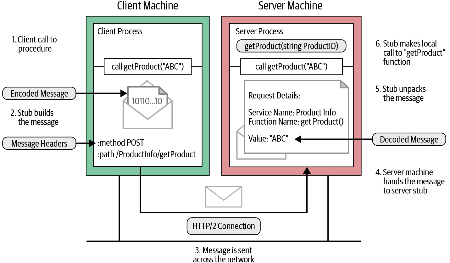
Figure 4-1. How a remote procedure call works over the network
As shown in Figure 4-1, we can identify the following key steps when the client calls the getProduct function in the generated stub:

The client process calls the
getProductfunction in the generated stub.
The client stub creates an HTTP POST request with the encoded message. In gRPC, all requests are HTTP POST requests with content-type prefixed with
application/grpc. The remote function (/ProductInfo/getProduct) that it invokes is sent as a separate HTTP header.
The HTTP request message is sent across the network to the server machine.

When the message is received at the server, the server examines the message headers to see which service function needs to be called and hands over the message to the service stub.

The service stub parses the message bytes into language-specific data structures.

Then, using the parsed message, the service makes a local call to the
getProductfunction.
The response from the service function is encoded and sent back to the client. The response message follows the same procedure that we observed on the client side (response→encode→HTTP response on the wire); the message is unpacked and its value returned to the waiting client process.
These steps are quite similar to most RPC systems like CORBA, Java RMI, etc. The main difference between gRPC here is the way that it encodes the message, which we saw in Figure 4-1. For encoding messages, gRPC uses protocol buffers. Protocol buffers are a language-agnostic, platform-neutral, extensible mechanism for serializing structured data. You define how you want your data to be structured once, then you can use the specially generated source code to easily write and read your structured data to and from a variety of data streams.
Let’s dive into how gRPC uses protocol buffers to encode messages.
Message Encoding Using Protocol Buffers
As we discussed in previous chapters, gRPC uses protocol buffers to write the service definition for gRPC services. Defining the service using protocol buffers includes defining remote methods in the service and defining messages we want to send across the network. For example, let’s take the getProduct method in the ProductInfo service. The getProduct method accepts a ProductID message as an input parameter and returns a Product message. We can define those input and output message structures using protocol buffers as shown in Example 4-1.
Example 4-1. Service definition of ProductInfo service with getProduct function
syntax="proto3";packageecommerce;serviceProductInfo{rpcgetProduct(ProductID)returns(Product);}messageProduct{stringid=1;stringname=2;stringdescription=3;floatprice=4;}messageProductID{stringvalue=1;}
As per Example 4-1, the ProductID message carries a unique product ID. So it has only one field with a string type. The Product message has the structure required to represent the product. It is important to have a message defined correctly, because how you define the message determines how the messages get encoded. We will discuss how message definitions are used when encoding messages later in this section.
Now that we have the message definition, let’s look at how to encode the message and generate the equivalent byte content. Normally this is handled by the generated source code for the message definition. All the supported languages have their own compilers to generate source code. As an application developer, you need to pass the message definition and generate source code to read and write the message.
Let’s say we need to get product details for product ID 15; we create a message object with value equal to 15 and pass it to the getProduct function. The following code snippet shows how to create a ProductID message with value equal to 15 and pass it to the getProduct function to retrieve product details:
product, err := c.GetProduct(ctx, &pb.ProductID{Value: “15”})
This code snippet is written in Go. Here, the ProductID message definition is in the generated source code. We create an instance of ProductID and set the value as 15. Similarly in the Java language, we use generated methods to create a ProductID instance as shown in the following code snippet:
ProductInfoOuterClass.Product product = stub.getProduct(
       ProductInfoOuterClass.ProductID.newBuilder()
               .setValue("15").build());
In the ProductID message structure that follows, there is one field called value with the field index 1. When we create a message instance with value equal to 15, the equivalent byte content consists of a field identifier for the value field followed by its encoded value. This field identifier is also known as a tag:
messageProductID{stringvalue=1;}
This byte content structure looks like Figure 4-2, where each message field consists of a field identifier followed by its encoded value.
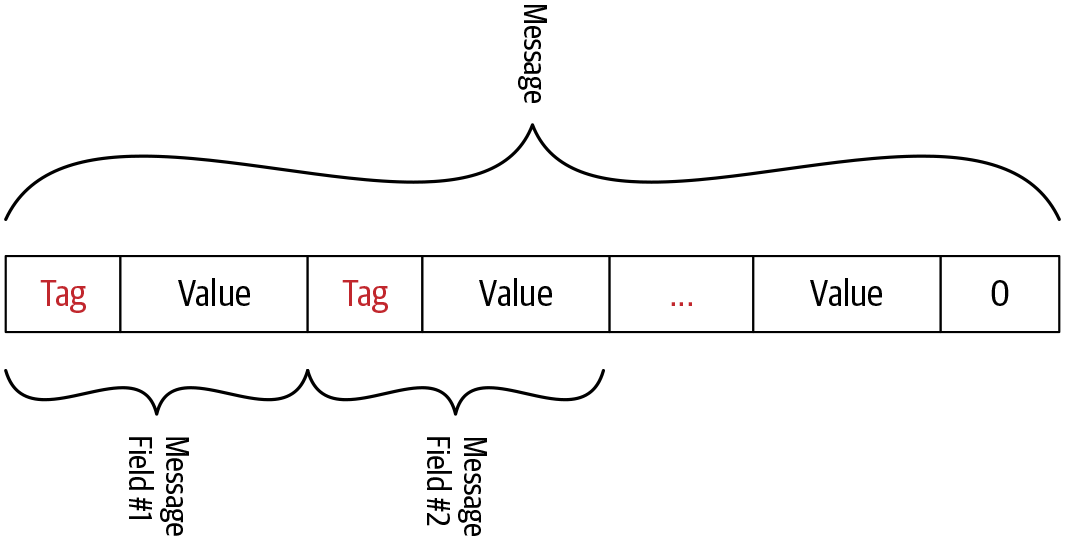
Figure 4-2. Protocol buffer encoded byte stream
This tag builds up two values: the field index and the wire type. The field index is the unique number we assigned to each message field when defining the message in the proto file. The wire type is based on the field type, which is the type of data that can enter the field. This wire type provides information to find the length of the value. Table 4-1 shows how wire types are mapped to field types. This is the predefined mapping of wire types and field types. You can refer to the official protocol buffers encoding document to get more insight into the mapping.
| Wire type | Category | Field types |
|---|---|---|
0 |
Varint |
int32, int64, uint32, uint64, sint32, sint64, bool, enum |
1 |
64-bit |
fixed64, sfixed64, double |
2 |
Length-delimited |
string, bytes, embedded messages, packed repeated fields |
3 |
Start group |
groups (deprecated) |
4 |
End group |
groups (deprecated) |
5 |
32-bit |
fixed32, sfixed32, float |
Once we know the field index and wire type of a certain field, we can determine the tag value of the field using the following equation. Here we left shift the binary representation of the field index by three digits and perform a bitwise union with the binary representation of the wire type value:
Tag value = (field_index << 3) | wire_type
Figure 4-3 shows how field index and wire type are arranged in a tag value.
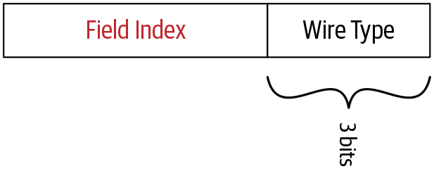
Figure 4-3. Structure of the tag value
Let’s try to understand this terminology using the example that we used earlier. The ProductID message has one string field with field index equal to 1 and the wire type of string is 2. When we convert them to binary representation, the field index looks like 00000001 and the wire type looks like 00000010. When we put those values into the preceding equation, the tag value 10 is derived as follows:
Tag value = (00000001 << 3) | 00000010
          = 000 1010
The next step is to encode the value of the message field. Different encoding techniques are used by protocol buffers to encode the different types of data. For example, if it is a string value, the protocol buffer uses UTF-8 to encode the value and if it is an integer value with the int32 field type, it uses an encoding technique called varints. We will discuss different encoding techniques and when those techniques are applied in the next section in detail. For now, we will discuss how to encode a string value to complete the example.
In protocol buffers encoding, string values are encoded using UTF-8 encoding technique. UTF (Unicode Transformation Format) uses 8-bit blocks to represent a character. It is a variable-length character encoding technique that is also a preferred encoding technique in web pages and emails.
In our example, the value of the value field in the ProductID message is 15 and the UTF-8 encoded value of 15 is \x31 \x35. In UTF-8 encoding, the encoded value length is not fixed. In other words, the number of 8-bit blocks required to represent the encoded value is not fixed. It varies based upon the value of the message field. In our example, it is two blocks. So we need to pass the encoded value length (number of blocks the encoded value spans) before the encoded value. The hexadecimal representation of the encoded value of 15 will look like this:
A 02 31 35
The two righthand bytes here are the UTF-8 encoded value of 15. Value 0x02 represents the length of the encoded string value in 8-bit blocks.
When a message is encoded, its tags and values are concatenated into a byte stream. Figure 4-2 illustrates how field values are arranged into a byte stream when a message has multiple fields. The end of the stream is marked by sending a tag valued 0.
We have now completed encoding a simple message with a string field using protocol buffers. The protocol buffers support various field types and some field types have different encoding mechanisms. Let’s quickly go through the encoding techniques used by protocol buffers.
Encoding Techniques
There are many encoding techniques supported by protocol buffers. Different encoding techniques are applied based on the type of data. For example, string values are encoded using UTF-8 character encoding, whereas int32 values are encoded using a technique called varints. Having knowledge about how data is encoded in each data type is important when designing the message definition because it allows us to set the most appropriate data type for each message field so that the messages are efficiently encoded at runtime.
In protocol buffers, supported field types are categorized into different groups and each group uses a different technique to encode the value. Listed in the next section are a few commonly used encoding techniques in protocol buffers.
Varints
Varints (variable length integers) are a method of serializing integers using one or more bytes. They’re based on the idea that most numbers are not uniformly distributed. So the number of bytes allocated for each value is not fixed. It depends on the value. As per Table 4-1, field types like int32, int64, uint32, uint64, sint32, sint64, bool, and enum are grouped into varints and encoded as varints. Table 4-2 shows what field types are categorized under varints, and what each type is used for.
| Field type | Definition |
|---|---|
|
A value type that represents signed integers with values that range from negative 2,147,483,648 to positive 2,147,483,647. Note this type is inefficient for encoding negative numbers. |
|
A value type that represents signed integers with values that range from negative 9,223,372,036,854,775,808 to positive 9,223,372,036,854,775,807. Note this type is inefficient for encoding negative numbers. |
|
A value type that represents unsigned integers with values that range from 0 to 4,294,967,295. |
|
A value type that represents unsigned integers with values that range from 0 to 18,446,744,073,709,551,615. |
|
A value type that represents signed integers with values that range from negative 2,147,483,648 to positive 2,147,483,647. This more efficiently encodes negative numbers than regular int32s. |
|
A value type that represents signed integers with values that range from negative 9,223,372,036,854,775,808 to positive 9,223,372,036,854,775,807. This more efficiently encodes negative numbers than regular int64s. |
|
A value type that represents two possible values, normally denoted as true or false. |
|
A value type that represents a set of named values. |
In varints, each byte except the last byte has the most significant bit (MSB) set to indicate that there are further bytes to come. The lower 7 bits of each byte are used to store the two’s complement representation of the number. Also, the least significant group comes first, which means that we should add a continuation bit to the low-order group.
Signed integers
Signed integers are types that represent both positive and negative integer values. Field types like sint32 and sint64 are considered signed integers. For signed types, zigzag encoding is used to convert signed integers to unsigned ones. Then unsigned integers are encoded using varints encoding as mentioned previously.
In zigzag encoding, signed integers are mapped to unsigned integers in a zigzag way through negative and positive integers. Table 4-3 shows how mapping works in zigzag encoding.
| Original value | Mapped value |
|---|---|
0 |
0 |
-1 |
1 |
1 |
2 |
-2 |
3 |
2 |
4 |
As shown in Table 4-3, value zero is mapped to the original value of zero and other values are mapped to positive numbers in a zigzag way. The negative original values are mapped to odd positive numbers and positive original values are mapped to even positive numbers. After zigzag encoding, we get a positive number irrespective of the sign of the original value. Once we have a positive number, we perform varints to encode the value.
For negative integer values, it is recommended to use signed integer types like sint32 and sint64 because if we use a regular type such as int32 or int64, negative values are converted to binary using varints encoding. Varints encoding for a negative integer value needs more bytes to represent an equivalent binary value than a positive integer value. So the efficient way of encoding negative value is to convert the negative value to a positive number and then encode the positive value. In signed integer types like sint32, the negative values are first converted to positive values using zigzag encoding and then encoded using varints.
Nonvarint numbers
Nonvarint types are just the opposite of the varint type. They allocate a fixed number of bytes irrespective of the actual value. Protocol buffers use two wire types that categorize as nonvarint numbers. One is for the 64-bit data types like fixed64, sfixed64, and double. The other is for 32-bit data types like fixed32, sfixed32, and float.
String type
In protocol buffers, the string type belongs to the length-delimited wire type, which means that the value is a varint-encoded length followed by the specified number of bytes of data. String values are encoded using UTF-8 character encoding.
We just summarized the techniques used to encode commonly used data types. You can find a detailed explanation about protocol buffer encoding on the official page.
Now that we have encoded the message using protocol buffers, the next step is to frame the message before sending it to the server over the network.
Length-Prefixed Message Framing
In common terms, the message-framing approach constructs information and communication so that the intended audience can easily extract the information. The same thing applies to gRPC communication as well. Once we have the encoded data to send to the other party, we need to package the data in a way that other parties can easily extract the information. In order to package the message to send over the network, gRPC uses a message-framing technique called length-prefix framing.
Length-prefix is a message-framing approach that writes the size of each message before writing the message itself. As you can see in Figure 4-4, before the encoded binary message there are 4 bytes allocated to specify the size of the message. In gRPC communication, 4 additional bytes are allocated for each message to set its size. The size of the message is a finite number, and allocating 4 bytes to represent the message size means gRPC communication can handle all messages up to 4 GB in size.
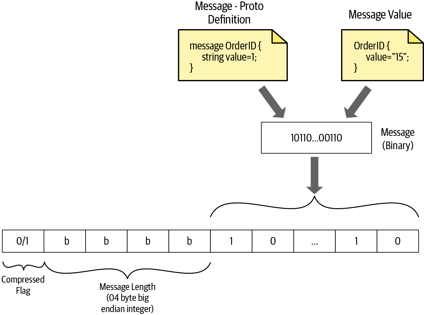
Figure 4-4. How a gRPC message frame uses length-prefix framing
As illustrated in Figure 4-4, when the message is encoded using protocol buffers, we get the message in binary format. Then we calculate the size of the binary content and add it before the binary content in big-endian format.
Note
Big-endian is a way of ordering binary data in the system or message. In big-endian format, the most significant value (the largest powers of two) in the sequence is stored at the lowest storage address.
In addition to the message size, the frame also has a 1-byte unsigned integer to indicate whether the data is compressed or not. A Compressed-Flag value of 1 indicates that the binary data is compressed using the mechanism declared in the Message-Encoding header, which is one of the headers declared in HTTP transport. The value 0 indicates that no encoding of message bytes has occurred. We will discuss HTTP headers supported in gRPC communication in detail in the next section.
So now the message is framed and it’s ready to be sent over the network to the recipient. For a client request message, the recipient is the server. For a response message, the recipient is the client. On the recipient side, once a message is received, it first needs to read the first byte to check whether the message is compressed or not. Then the recipient reads the next four bytes to get the size of the encoded binary message. Once the size is known, the exact length of bytes can be read from the stream. For unary/simple messages, we will have only one length-prefixed message, and for streaming messages, we will have multiple length-prefixed messages to process.
Now you have a good understanding of how messages are prepared to deliver to the recipient over the network. In the next section, we are going to discuss how gRPC sends those length-prefixed messages over the network. Currently, the gRPC core supports three transport implementations: HTTP/2, Cronet, and in-process. Among them, the most common transport for sending messages is HTTP/2. Let’s discuss how gRPC utilizes the HTTP/2 network to send messages efficiently.
gRPC over HTTP/2
HTTP/2 is the second major version of the internet protocol HTTP. It was introduced to overcome some of the issues encountered with security, speed, etc. in the previous version (HTTP/1.1). HTTP/2 supports all of the core features of HTTP/1.1 but in a more efficient way. So applications written in HTTP/2 are faster, simpler, and more robust.
gRPC uses HTTP/2 as its transport protocol to send messages over the network. This is one of the reasons why gRPC is a high-performance RPC framework. Let’s explore the relationship between gRPC and HTTP/2.
Note
In HTTP/2, all communication between a client and server is performed over a single TCP connection that can carry any number of bidirectional flows of bytes. To understand the HTTP/2 process, you should be familiar with the following important terminology:
-
Stream: A bidirectional flow of bytes within an established connection. A stream may carry one or more messages.
-
Frame: The smallest unit of communication in HTTP/2. Each frame contains a frame header, which at a minimum identifies the stream to which the frame belongs.
-
Message: A complete sequence of frames that map to a logical HTTP message that consists of one or more frames. This allows the messages to be multiplexed, by allowing the client and server to break down the message into independent frames, interleave them, and then reassemble them on the other side.
As you can see in Figure 4-5, the gRPC channel represents a connection to an endpoint, which is an HTTP/2 connection. When the client application creates a gRPC channel, behind the scenes it creates an HTTP/2 connection with the server. Once the channel is created we can reuse it to send multiple remote calls to the server. These remote calls are mapped to streams in HTTP/2. Messages that are sent in the remote call are sent as HTTP/2 frames. A frame may carry one gRPC length-prefixed message, or if a gRPC message is quite large it might span multiple data frames.
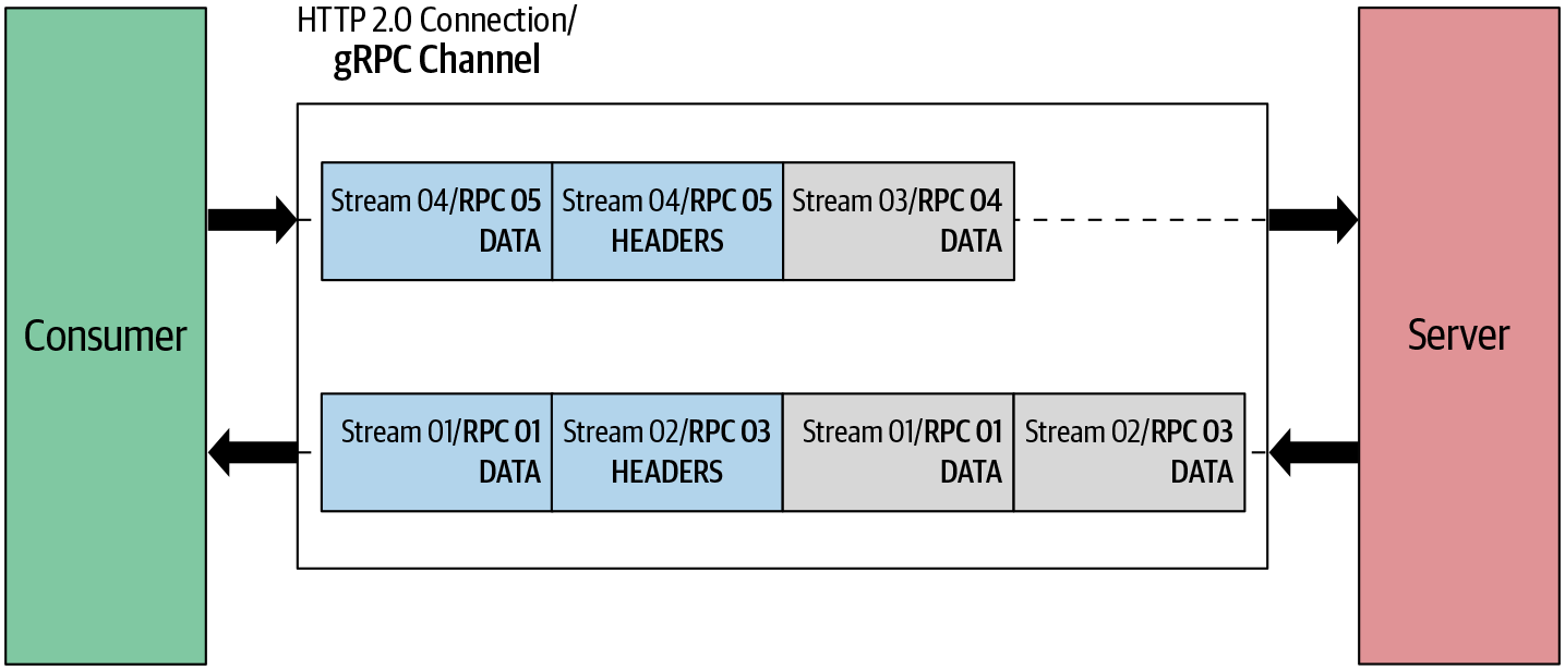
Figure 4-5. How gRPC semantics relate to HTTP/2
In the previous section, we discussed how to frame our message to a length-prefixed message. When we send them over the network as a request or response message, we need to send additional headers along with the message. Let’s discuss how to structure request/response messages and which headers need to pass for each message in the next sections.
Request Message
The request message is the one that initiates the remote call. In gRPC, the request message is always triggered by the client application and it consists of three main components: request headers, the length-prefixed message, and the end of stream flag as shown in Figure 4-6. The remote call is initiated once the client sends request headers. Then, length-prefixed messages are sent in the call. Finally, the EOS (end of stream) flag is sent to notify the recipient that we finished sending the request message.

Figure 4-6. Sequence of message elements in request message
Let’s use the same getProduct function in the ProductInfo service to explain how the request message is sent in HTTP/2 frames. When we call the getProduct function, the client initiates a call by sending request headers as shown here:
HEADERS (flags = END_HEADERS) :method = POST:scheme = http
:path = /ProductInfo/getProduct
:authority = abc.com
te = trailers
grpc-timeout = 1S
content-type = application/grpc
grpc-encoding = gzip
authorization = Bearer xxxxxx

Defines the HTTP method. For gRPC, the
:methodheader is alwaysPOST.
Defines the HTTP scheme. If TLS (Transport Level Security) is enabled, the scheme is set to “https,” otherwise it is “http.”

Defines the endpoint path. For gRPC, this value is constructed as “/” {service name} “/” {method name}.

Defines the virtual hostname of the target URI.

Defines detection of incompatible proxies. For gRPC, the value must be “trailers.”

Defines call timeout. If not specified, the server should assume an infinite timeout.

Defines the content-type. For gRPC, the content-type should begin with
application/grpc. If not, gRPC servers will respond with an HTTP status of 415 (Unsupported Media Type).
Defines the message compression type. Possible values are
identity,gzip,deflate,snappy, and{custom}.
This is optional metadata.
authorizationmetadata is used to access the secure endpoint.
Note
Some other notes on this example:
-
Header names starting with “:” are called reserved headers and HTTP/2 requires reserved headers to appear before other headers.
-
Headers passed in gRPC communication are categorized into two types: call-definition headers and custom metadata.
-
Call-definition headers are predefined headers supported by HTTP/2. Those headers should be sent before custom metadata.
-
Custom metadata is an arbitrary set of key-value pairs defined by the application layer. When you are defining custom metadata, you need to make sure not to use a header name starting with
grpc-. This is listed as a reserved name in the gRPC core.
Once the client initiates the call with the server, the client sends length-prefixed messages as HTTP/2 data frames. If the length-prefixed message doesn’t fit one data frame, it can span to multiple data frames. The end of the request message is indicated by adding an END_STREAM flag on the last DATA frame. When no data remains to be sent but we need to close the request stream, the implementation must send an empty data frame with the END_STREAM flag:
DATA (flags = END_STREAM)
<Length-Prefixed Message>
This is just an overview of the structure of the gRPC request message. You can find more details in the official gRPC GitHub repository.
Similar to the request message, the response message also has its own structure. Let’s look at the structure of response messages and the related headers.
Response Message
The response message is generated by the server in response to the client’s request. Similar to the request message, in most cases the response message also consists of three main components: response headers, length-prefixed messages, and trailers. When there is no length-prefixed message to send as a response to the client, the response message consists only of headers and trailers as shown in Figure 4-7.

Figure 4-7. Sequence of message elements in a response message
Let’s look at the same example to explain the HTTP/2 framing sequence of the response message. When the server sends a response to the client, it first sends response headers as shown here:
HEADERS (flags = END_HEADERS) :status = 200grpc-encoding = gzip
content-type = application/grpc

Indicates the status of the HTTP request.

Defines the message compression type. Possible values include
identity,gzip,deflate,snappy, and{custom}.
Defines the
content-type. For gRPC, thecontent-typeshould begin withapplication/grpc.
Note
Similar to the request headers, custom metadata that contains an arbitrary set of key-value pairs defined by the application layer can be set in the response headers.
Once the server sends response headers, length-prefixed messages are sent as HTTP/2 data frames in the call. Similar to the request message, if the length-prefixed message doesn’t fit one data frame, it can span to multiple data frames. As shown in the following, the END_STREAM flag isn’t sent with data frames. It is sent as a separate header called a trailer:
DATA
<Length-Prefixed Message>
In the end, trailers are sent to notify the client that we finished sending the response message. Trailers also carry the status code and status message of the request:
HEADERS (flags = END_STREAM, END_HEADERS) grpc-status = 0 # OKgrpc-message = xxxxxx

Defines the gRPC status code. gRPC uses a set of well-defined status codes. You can find the definition of status codes in the official gRPC documentation.

Defines the description of the error. This is optional. This is only set when there is an error in processing the request.
Note
Trailers are also delivered as HTTP/2 header frames but at the end of the response message. The end of the response stream is indicated by setting the END_STREAM flag in trailer headers. Additionally, it contains the grpc-status and grpc-message headers.
In certain scenarios, there can be an immediate failure in the request call. In those cases, the server needs to send a response back without the data frames. So the server sends only trailers as a response. Those trailers are also delivered as an HTTP/2 header frame and also contain the END_STREAM flag. Additionally, the following headers are included in trailers:
-
HTTP-Status →
:status -
Content-Type →
content-type -
Status →
grpc-status -
Status-Message →
grpc-message
Now that we know how a gRPC message flows over an HTTP/2 connection, let’s try to understand the message flow of different communication patterns in gRPC.
Understanding the Message Flow in gRPC Communication Patterns
In the previous chapter, we discussed four communication patterns supported by gRPC. They are simple RPC, server-streaming RPC, client-streaming RPC, and bidirectional-streaming RPC. We also discussed how those communication patterns work using real-world use cases. In this section, we are going to look at those patterns again from a different angle. Let’s discuss how each pattern works at the transport level with the knowledge we collected in this chapter.
Simple RPC
In simple RPC you always have a single request and a single response in the communication between the gRPC server and gRPC client. As shown in Figure 4-8, the request message contains headers followed by a length-prefixed message, which can span one or more data frames. An end of stream (EOS) flag is added at the end of the message to half-close the connection at the client side and mark the end of the request message. Here “half-close the connection” means the client closes the connection on its side so the client is no longer able to send messages to the server but still can listen to the incoming messages from the server. The server creates the response message only after receiving the complete message on the server side. The response message contains a header frame followed by a length-prefixed message. Communication ends once the server sends the trailing header with status details.
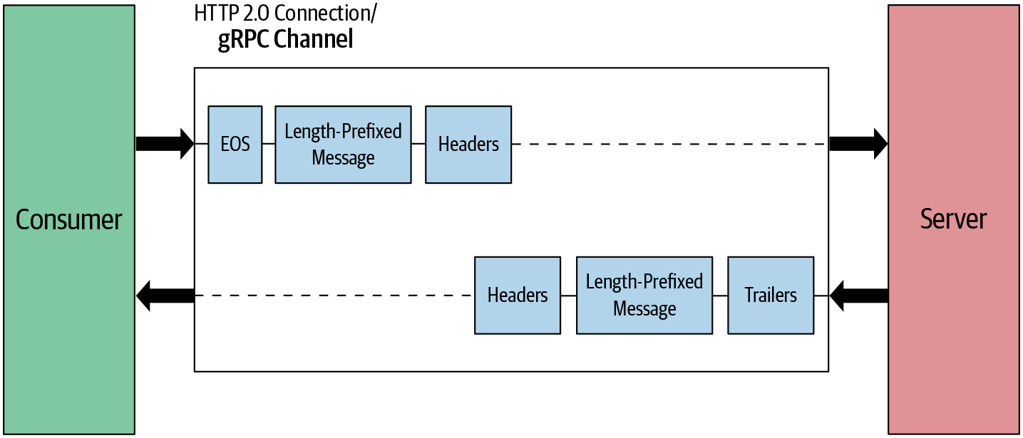
Figure 4-8. Simple RPC: message flow
This is the simplest communication pattern. Let’s move on to a bit more complex server-streaming RPC scenario.
Server-streaming RPC
From the client perspective, both simple RPC and server-streaming RPC have the same request message flow. In both cases, we send one request message. The main difference is on the server side. Rather than sending one response message to the client, the server sends multiple messages. The server waits until it receives the completed request message and sends the response headers and multiple length-prefixed messages as shown in Figure 4-9. Communication ends once the server sends the trailing header with status details.
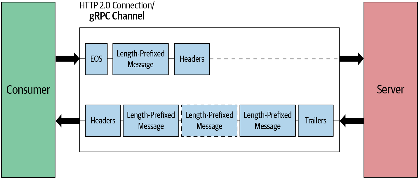
Figure 4-9. Server-streaming RPC: message flow
Now let’s look at client-streaming RPC, which is pretty much the opposite of server-streaming RPC.
Client-streaming RPC
In client-streaming RPC, the client sends multiple messages to the server and the server sends one response message in reply. The client first sets up the connection with the server by sending the header frames. Once the connection is set up, the client sends multiple length-prefixed messages as data frames to the server as shown in Figure 4-10. In the end, the client half-closes the connection by sending an EOS flag in the last data frame. In the meantime, the server reads the messages received from the client. Once it receives all messages, the server sends a response message along with the trailing header and closes the connection.
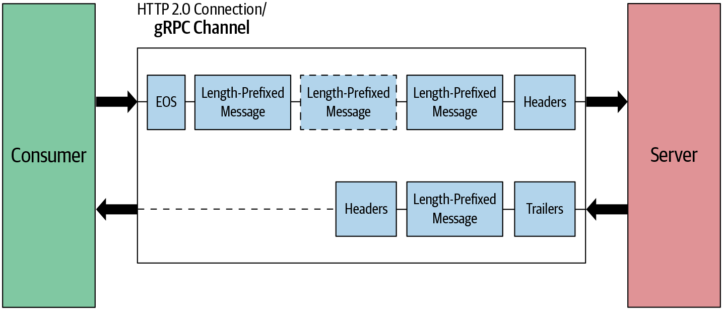
Figure 4-10. Client-streaming RPC: message flow
Now let’s move onto the last communication pattern, bidirectional RPC, in which the client and server are both sending multiple messages to each other until they close the connection.
Bidirectional-streaming RPC
In this pattern, the client sets up the connection by sending header frames. Once the connection is set up, the client and server both send length-prefixed messages without waiting for the other to finish. As shown in Figure 4-11, both client and server send messages simultaneously. Both can end the connection at their side, meaning they can’t send any more messages.
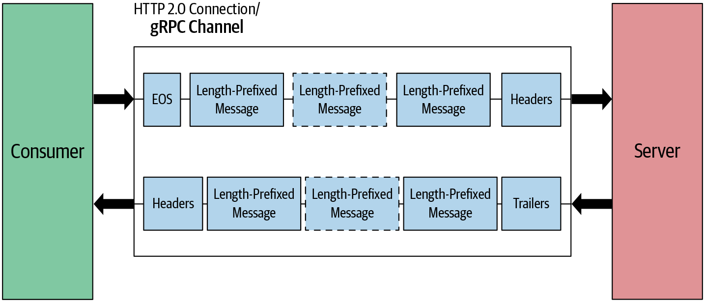
Figure 4-11. Bidirectional-streaming RPC: message flow
With that, we have come to the end of our in-depth tour of gRPC communication. Network and transport-related operations in communication are normally handled at the gRPC core layer and you don’t need to be aware of the details as a gRPC application developer.
Before wrapping up this chapter, let’s look at the gRPC implementation architecture and the language stack.
gRPC Implementation Architecture
As shown in Figure 4-12, gRPC implementation can be divided into multiple layers. The base layer is the gRPC core layer. It is a thin layer and it abstracts all the network operations from the upper layers so that application developers can easily make RPC calls over the network. The core layer also provides extensions to the core functionality. Some of the extension points are authentication filters to handle call security and a deadline filter to implement call deadlines, etc.
gRPC is natively supported by the C/C++, Go, and Java languages. gRPC also provides language bindings in many popular languages such as Python, Ruby, PHP, etc. These language bindings are wrappers over the low-level C API.
Finally, the application code goes on top of language bindings. This application layer handles the application logic and data encoding logic. Normally developers generate source code for data encoding logic using compilers provided by different languages. For example, if we use protocol buffers for encoding data, the protocol buffer compiler can be used to generate source code. So developers can write their application logic by invoking the methods of generated source code.
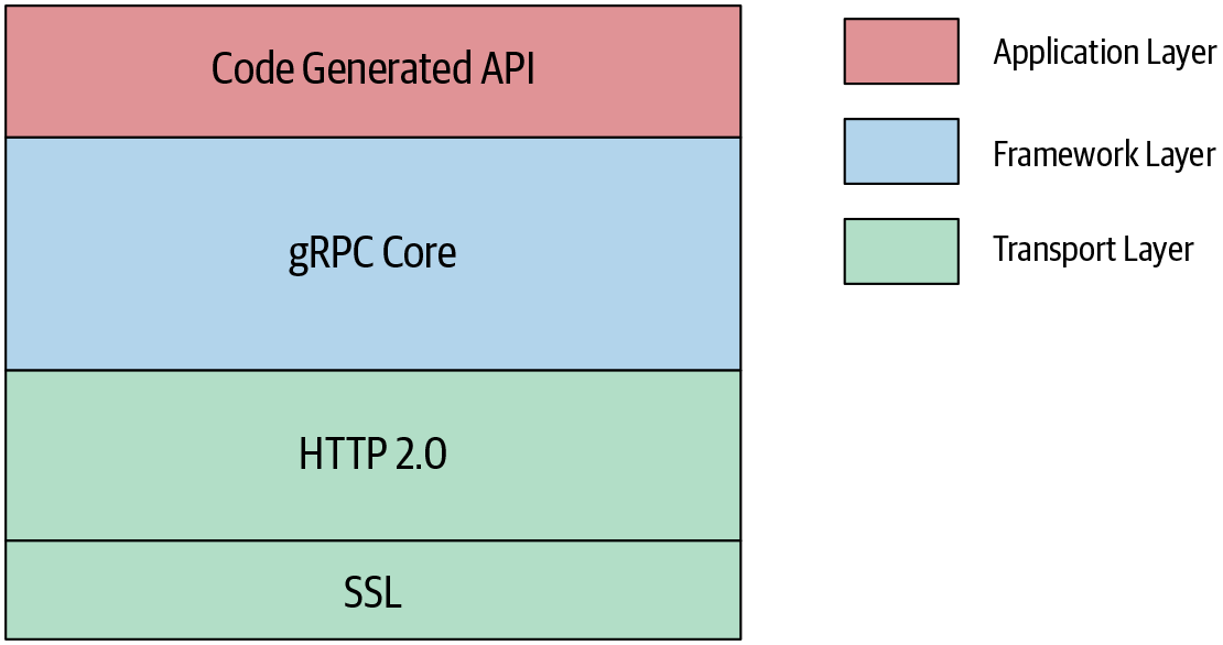
Figure 4-12. gRPC native implementation architecture
With that, we have covered most of the low-level implementation and execution details of gRPC-based applications. As an application developer, it is always better to have an understanding of the low-level details about the techniques you’re going to use in the application. It not only helps to design robust applications, but also helps in troubleshooting application issues easily.
Summary
gRPC builds on top of two fast and efficient protocols called protocol buffers and HTTP/2. Protocol buffers are a data serialization protocol that is a language-agnostic, platform-neutral, and extensible mechanism for serializing structured data. Once serialized, this protocol produces a binary payload that is smaller in size than a normal JSON payload and is strongly typed. This serialized binary payload then travels over the binary transport protocol called HTTP/2.
HTTP/2 is the next major version of the internet protocol HTTP. HTTP/2 is fully multiplexed, which means that HTTP/2 can send multiple requests for data in parallel over a single TCP connection. This makes applications written in HTTP/2 faster, simpler, and more robust than others.
All these factors make gRPC a high-performance RPC framework.
In this chapter we covered low-level details about gRPC communication. These details may be not essential to develop a gRPC application, because they are already handled by the library, but understanding low-level gRPC message flow is absolutely essential when it comes to troubleshooting gRPC communication-related issues when you use gRPC in production. In the next chapter, we’ll discuss some advanced capabilities provided by gRPC to cater to real-world requirements.
Get gRPC: Up and Running now with the O’Reilly learning platform.
O’Reilly members experience books, live events, courses curated by job role, and more from O’Reilly and nearly 200 top publishers.

