Fig. 1-1. Earth regimes of concern for on-orbit surface charging hazards for spacecraft passing through the latitude and altitude indicated. See Whittlesey et al. [9] for an alternative reference with the ``Wishbone'' chart. (From [8].)
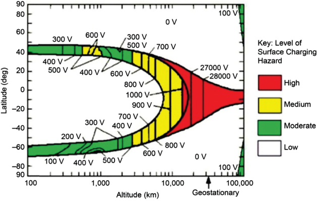
Fig. 1-2. Earth regimes of concern for on-orbit internal charging hazards for spacecraft with circular orbits.
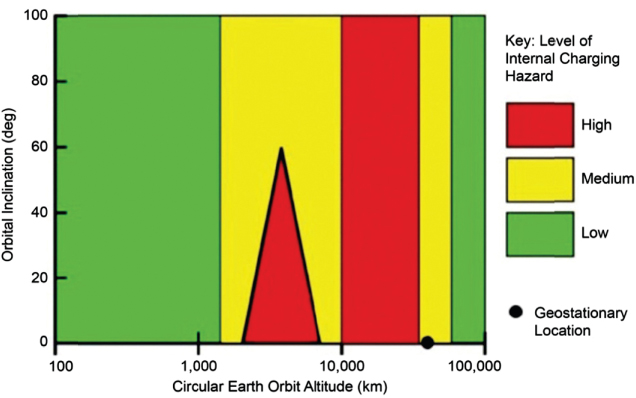
Fig. 3-2. Examples of solar array failures caused by (a) in-flight arcing (from [15]) and (b) ground ESD arcing.
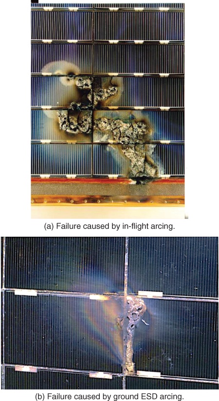
Fig. 3-3. Measured gallium arsenide (GaAs) coupon I/V failure threshold (From [3].)
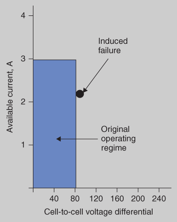
Fig. 3-4. Measured silicon (Si) coupon I/V failure threshold (From [3].)
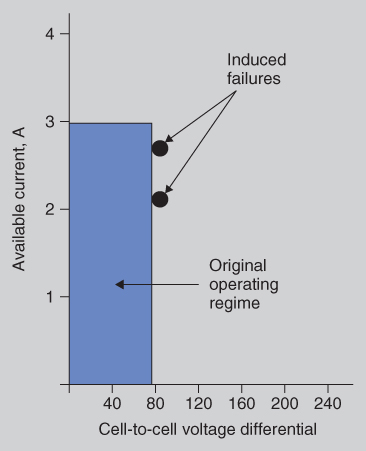
Fig. 6-1. Safe, intermediate, and possibly hazardous dielectric materials based on resistivity and dielectric constant and resulting time constant. (The Kapton© and Teflon© boxes illustrate the uncertainty range for space applications; see the text.)
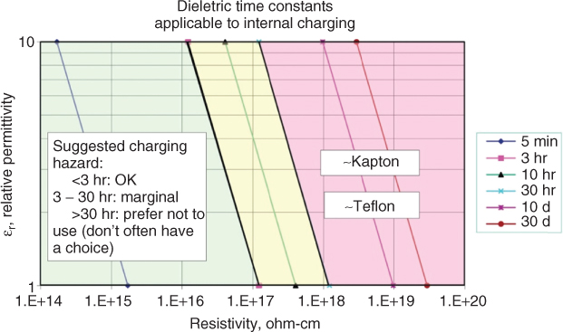
Fig. B-7. Cumulative ...
Get Guide to Mitigating Spacecraft Charging Effects now with the O’Reilly learning platform.
O’Reilly members experience books, live events, courses curated by job role, and more from O’Reilly and nearly 200 top publishers.

