200 IBM eX5 Implementation Guide
fashion to provide a balanced system and populating all processors identically is also
required by VMware.
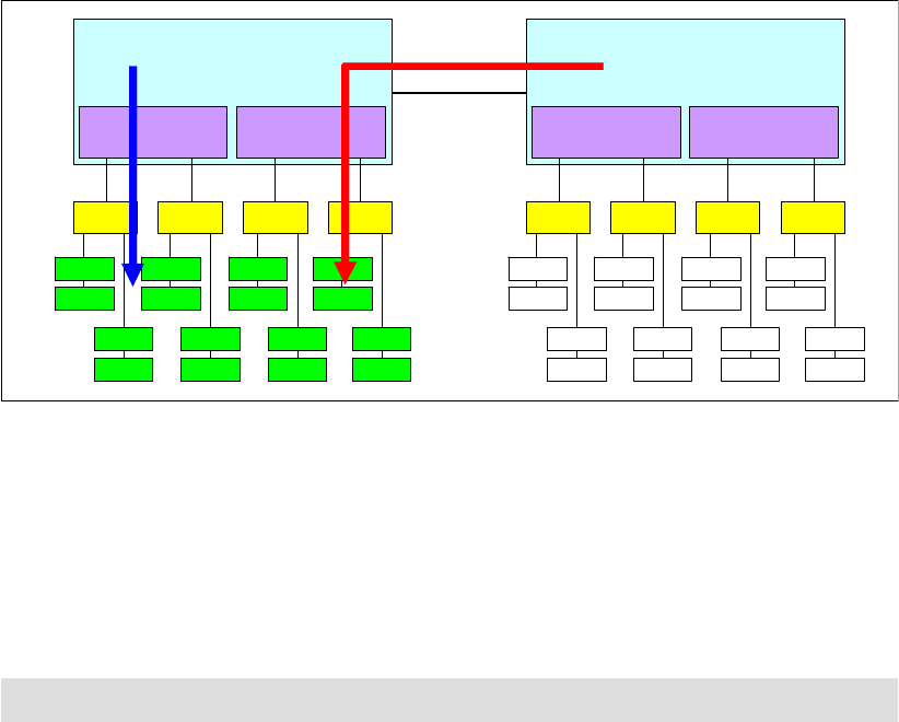
Looking at Figure 5-16 as an example, Processor 0 has DIMMs populated, but no DIMMs are
populated that are connected to Processor 1. In this case, Processor 0 has access to
low-latency local memory and high-memory bandwidth. However, Processor 1 has access
only to remote or “far” memory. So, threads executing on Processor 1 have a longer latency to
access memory as compared to threads on Processor 0. This result is due to the latency
penalty incurred to traverse the QPI links to access the data on the other processor’s memory
controller. The bandwidth to remote memory is also limited by the capability of the QPI links.
The latency to access remote memory is more than 50% higher than local memory access.
For these reasons, we advise that you populate all of the processors with memory,
remembering the necessary requirements to ensure optimal interleaving and Hemisphere
Mode.
Figure 5-16 Memory latency when not spreading DIMMs across both processors
5.10.4 Memory mirroring
Memory mirroring is supported using HX5 and MAX5. On the HX5, when enabled, the first
DIMM quadrant is duplicated onto the second DIMM quadrant for each processor. For a
detailed understanding of memory mirroring, see “Memory mirroring” on page 28.
This section contains DIMM placements for each solution.
DIMM placement: HX5
Table 5-17 on page 201 lists the DIMM installation sequence for memory-mirroring mode
when one processor is installed.
QPI links
Intel Xeon 7500
Processor 0
DIMM
DIMM
DIMM
DIMM
DIMM
DIMM
DIMM
DIMM
DIMM
DIMM
DIMM
DIMM
DIMM
DIMM
DIMM
DIMM
DIMM
DIMM
DIMMDIMM
Buffer Buffer Buffer Buffer
Memory
controller
Memory
controller
Intel Xeon 7500
Processor 1
DIMM
DIMM
DIMMDIMM
Buffer Buffer Buffer Buffer
Memory
controller
Memory
controller
LOCAL
REMOTE
Important: If using memory mirroring, all DIMMs must be identical in size and rank.
Chapter 5. IBM BladeCenter HX5 201
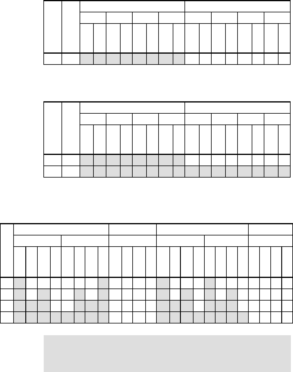
Table 5-17 DIMM installation for memory mirroring: One processor
Table 5-18 lists the DIMM installation sequence for memory-mirroring mode when two
processors are installed.
Table 5-18 DIMM installation for memory mirroring: Two processors
DIMM placement: MAX5
Table 5-19 lists the DIMM installation sequence in the MAX5 for memory-mirroring mode.
Only power domains A and B are populated.
Table 5-19 DIMM installation for the MAX5 memory mirroring for IBM BladeCenter
Number of
processors
Number of
DIMMs
Processor 1 Processor 2
Buffer Buffer Buffer Buffer Buffer Buffer Buffer Buffer
DIMM 1
DIMM 2
DIMM 3
DIMM 4
DIMM 5
DIMM 6
DIMM 7
DIMM 8
DIMM 9
DIMM 10
DIMM 11
DIMM 12
DIMM 13
DIMM 14
DIMM 15
DIMM 16
18x x x x x x x x
Number of
processors
Number of
DIMMs
Processor 1 Processor 2
Buffer Buffer Buffer Buffer Buffer Buffer Buffer Buffer
DIMM 1
DIMM 2
DIMM 3
DIMM 4
DIMM 5
DIMM 6
DIMM 7
DIMM 8
DIMM 9
DIMM 10
DIMM 11
DIMM 12
DIMM 13
DIMM 14
DIMM 15
DIMM 16
18x x x x x x x x
116
x x x x x x x x x x x x x x x x
Number of DIMMs
Power domain A Domain C (½) Power domain B Domain C (½)
Buffer Buffer Buffer Buffer Buffer Buffer
DIMM 1
DIMM 2
DIMM 3
DIMM 4
DIMM 5
DIMM 6
DIMM 7
DIMM 8
DIMM 9
DIMM 10
DIMM 11
DIMM 12
DIMM 13
DIMM 14
DIMM 15
DIMM 16
DIMM 17
DIMM 18
DIMM 19
DIMM 20
DIMM 21
DIMM 22
DIMM 23
DIMM 24
4 x x x x
8 x x x x x x x x
12 x x x x x x x x x x x x
16 x x x x x x x x x x x x x x x x
Domain C must be empty: Memory mirroring is only supported using two domains. You
must remove all DIMMs from Domain C. If there is memory in Domain C, you get the
following error in the AMM logs and all memory in the MAX5 is disabled:
“Group 1, (memory device 1-40) (All DIMMs) memory configuration error”
Get IBM eX5 Implementation Guide now with the O’Reilly learning platform.
O’Reilly members experience books, live events, courses curated by job role, and more from O’Reilly and nearly 200 top publishers.

