Juniper Networks prides itself on creating custom silicon and making history with silicon firsts. Trio is the latest milestone:
1998: First separation of control and data plane
1998: First implementation of IPv4, IPv6, and MPLS in silicon
2000: First line-rate 10 Gbps forwarding engine
2004: First multi-chassis router
2005: First line-rate 40 Gbps forwarding engine
2007: First 160 Gbps firewall
2009: Next generation silicon: Trio
2010: First 130 Gbps PFE; next generation Trio
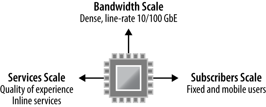
Trio is a fundamental technology asset for Juniper that combines three major components: bandwidth scale, services scale, and subscriber scale. Trio was designed from the ground up to support high-density, line-rate 10G and 100G ports. Inline services such as IPFLOW, NAT, GRE, and BFD offer a higher level of quality of experience without requiring an additional services card. Trio offers massive subscriber scale in terms of logical interfaces, IPv4 and IPv6 routes, and hierarchical queuing.
Trio is built upon a Network Instruction Set Processor (NISP). The key differentiator is that Trio has the performance of a traditional ASIC, but the flexibility of a field-programmable gate array (FPGA) by allowing the installation of new features via software. Here is just an example of the inline services available with the Trio chipset:
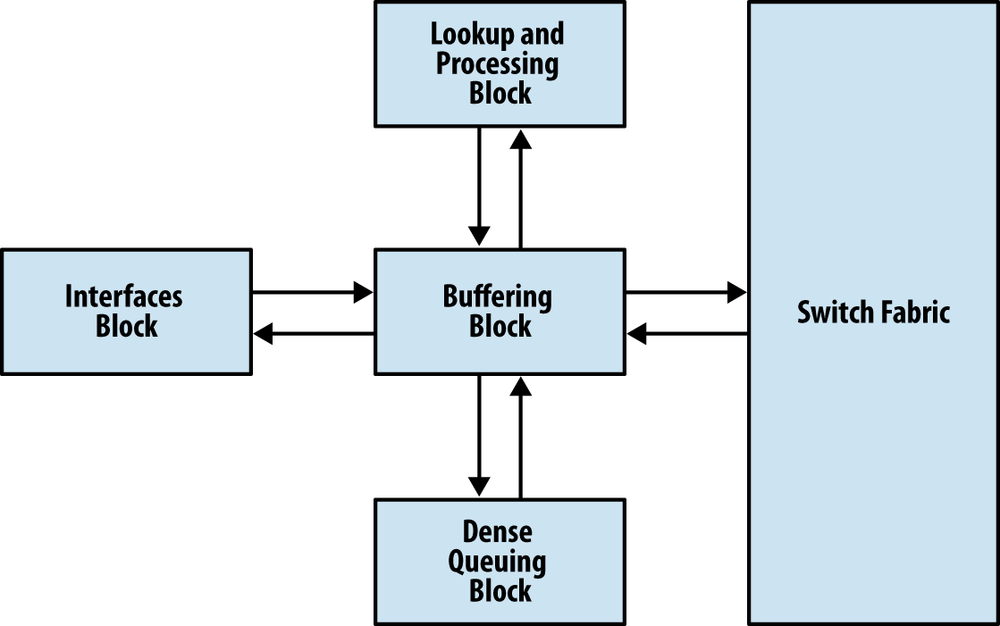
The Trio chipset comprises of four major building blocks: Buffering, Lookup, Interfaces, and Dense Queuing.
Each function is separated into its own block so that each function is highly optimized and cost efficient. Depending on the size and scale required, Trio is able to take these building blocks and create line cards that offer specialization such as hierarchical queuing or intelligent oversubscription.
The Buffering Block ties together all of the other functional Trio blocks. It primarily manages packet data, fabric queuing, and revenue port queuing. The interesting thing to note about the Buffering Block is that it’s possible to delegate responsibilities to other functional Trio blocks. As of the writing of this book, there are two primary use cases for delegating responsibility: process oversubscription and revenue port queuing.
In the scenario where the number of revenue ports on a single MIC is less than 24x1GE or 2x10GE, it’s possible to move the handling of oversubscription to the Interfaces Block. This opens doors to creating oversubscribed line cards at an attractive price point that are able to handle oversubscription intelligently by allowing control plane and voice data to be processed during congestion.
The Buffering Block is able to process basic per port queuing. Each port has eight hardware queues, large delay buffers, and low latency queues (LLQs). If there’s a requirement to have hierarchical class of service (H-QoS) and additional scale, this functionality can be delegated to the Dense Queuing Block.
The Lookup Block has multi-core processors to support parallel tasks using multiple threads. This is the bread and butter of Trio. The Lookup Block supports all of the packet header processing such as:
Route lookups
MAC lookups
Class of Service (QoS) Classification
Firewall filters
Policers
Accounting
Encapsulation
Statistics
A key feature in the Lookup Block is that it supports Deep Packet Inspection (DPI) and is able to look over 256 bytes into the packet. This creates interesting features such as Distributed Denial of Service (DDoS) protection, which is covered in Chapter 4.
As packets are received by the Buffering Block, the packet headers are sent to the Lookup Block for additional processing. All processing is completed in one pass through the Lookup Block regardless of the complexity of the workflow. Once the Lookup Block has finished processing, it sends the modified packet headers back to the Buffering Block to send the packet to its final destination.
In order to process data at line rate, the Lookup Block has a large bucket of reduced-latency dynamic random access memory (RLDRAM) that is essential for packet processing.
Let’s take a quick peek at the current memory utilization in the Lookup Block.
{master}
dhanks@R1-RE0> request pfe execute target fpc2 command "show jnh 0 pool usage"
SENT: Ukern command: show jnh 0 pool usage
GOT:
GOT: EDMEM overall usage:
GOT: [NH///|FW///|CNTR//////|HASH//////|ENCAPS////|--------------]
GOT: 0     2.0   4.0        9.0        16.8       20.9           32.0M
GOT:
GOT: Next Hop
GOT: [*************|-------] 2.0M (65% | 35%)
GOT:
GOT: Firewall
GOT: [|--------------------] 2.0M (1% | 99%)
GOT:
GOT: Counters
GOT: [|----------------------------------------] 5.0M (<1% | >99%)
GOT:
GOT: HASH
GOT: [*********************************************] 7.8M (100% | 0%)
GOT:
GOT: ENCAPS
GOT: [*****************************************] 4.1M (100% | 0%)
GOT:
LOCAL: End of file
The external data memory (EDMEM) is responsible for storing all of the firewall filters, counters, next-hops, encapsulations, and hash data. These values may look small, but don’t be fooled. In our lab, we have an MPLS topology with over 2,000 L3VPNs including BGP route reflection. Within each VRF there is a firewall filter applied with two terms. As you can see, the firewall memory is barely being used. These memory allocations aren’t static and are allocated as needed. There is a large pool of memory and each EDMEM attribute can grow as needed.
One of the optional components is the Interfaces Block. Its primary responsibility is to intelligently handle oversubscription. When using a MIC that supports less than 24x1GE or 2x10GE MACs, the Interfaces Block is used to manage the oversubscription.
Note
As new MICs are released, they may or may not have an Interfaces Block depending on power requirements and other factors. Remember that the Trio function blocks are like building blocks and some blocks aren’t required to operate.
Each packet is inspected at line rate, and attributes such as Ethernet Type Codes, Protocol, and other Layer 4 information are used to evaluate which buffers to enqueue the packet towards the Buffering Block. Preclassification allows the ability to drop excess packets as close to the source as possible, while allowing critical control plane packets through to the Buffering Block.
There are four queues between the Interfaces and Buffering Block: real-time, control traffic, best effort, and packet drop. Currently, these queues and preclassifications are not user configurable; however, it’s possible to take a peek at them.
Let’s take a look at a router with a 20x1GE MIC that has an Interfaces Block.
dhanks@MX960> show chassis hardware
Hardware inventory:
Item             Version  Part number  Serial number     Description
Chassis                                JN10852F2AFA      MX960
Midplane         REV 02   710-013698   TR0019            MX960 Backplane
FPM Board        REV 02   710-014974   JY4626            Front Panel Display
Routing Engine 0 REV 05   740-031116   9009066101        RE-S-1800x4
Routing Engine 1 REV 05   740-031116   9009066210        RE-S-1800x4
CB 0             REV 10   750-031391   ZB9999            Enhanced MX SCB
CB 1             REV 10   750-031391   ZC0007            Enhanced MX SCB
CB 2             REV 10   750-031391   ZC0001            Enhanced MX SCB
FPC 1            REV 28   750-031090   YL1836            MPC Type 2 3D EQ
  CPU            REV 06   711-030884   YL1418            MPC PMB 2G
  MIC 0          REV 05   750-028392   JG8529            3D 20x 1GE(LAN) SFP
  MIC 1          REV 05   750-028392   JG8524            3D 20x 1GE(LAN) SFP
We can see that FPC1 supports two 20x1GE MICs. Let’s take a peek at the preclassification on FPC1.
dhanks@MX960> request pfe execute target fpc1 command "show precl-eng summary"
SENT: Ukern command: show precl-eng summary
GOT:
GOT:  ID  precl_eng name       FPC PIC   (ptr)
GOT: --- -------------------- ---- ---  --------
GOT:   1 IX_engine.1.0.20       1   0  442484d8
GOT:   2 IX_engine.1.1.22       1   1  44248378
LOCAL: End of file
It’s interesting to note that there are two preclassification engines. This makes sense as there is an Interfaces Block per MIC. Now let’s take a closer look at the preclassification engine and statistics on the first MIC.
dhanks@MX960> request pfe execute target fpc1 command "show precl-eng 1 statistics"
SENT: Ukern command: show precl-eng 1 statistics
GOT:
GOT:          stream    Traffic
GOT:  port      ID       Class         TX pkts         RX pkts        Dropped pkts
GOT: ------  -------  ----------       ---------       ------------   ------------
GOT:   00      1025        RT          000000000000    000000000000   000000000000
GOT:   00      1026        CTRL        000000000000    000000000000   000000000000
GOT:   00      1027        BE          000000000000    000000000000   000000000000
Each physical port is broken out and grouped by traffic class. The number of packets dropped is maintained in a counter on the last column. This is always a good place to look if the router is oversubscribed and dropping packets.
Let’s take a peek at a router with a 4x10GE MIC that doesn’t have an Interfaces Block.
{master}
dhanks@R1-RE0> show chassis hardware
Hardware inventory:
Item             Version  Part number  Serial number     Description
Chassis                                JN111992BAFC      MX240
Midplane         REV 07   760-021404   TR5026            MX240 Backplane
FPM Board        REV 03   760-021392   KE2411            Front Panel Display
Routing Engine 0 REV 07   740-013063   1000745244        RE-S-2000
Routing Engine 1 REV 06   740-013063   1000687971        RE-S-2000
CB 0             REV 03   710-021523   KH6172            MX SCB
CB 1             REV 10   710-021523   ABBM2781          MX SCB
FPC 2            REV 25   750-031090   YC5524            MPC Type 2 3D EQ
  CPU            REV 06   711-030884   YC5325            MPC PMB 2G
  MIC 0          REV 24   750-028387   YH1230            3D 4x 10GE  XFP
  MIC 1          REV 24   750-028387   YG3527            3D 4x 10GE  XFP
Here we can see that FPC2 has two 4x10GE MICs. Let’s take a closer look and the preclassification engines.
{master}
dhanks@R1-RE0> request pfe execute target fpc2 command "show precl-eng summary"
SENT: Ukern command: show precl-eng summary
GOT:
GOT:  ID  precl_eng name       FPC PIC   (ptr)
GOT: --- -------------------- ---- ---  --------
GOT:   1 MQ_engine.2.0.16       2   0  435e2318
GOT:   2 MQ_engine.2.1.17       2   1  435e21b8
LOCAL: End of file
The big difference here is the preclassification engine name. Previously, it was listed as “IX_engine” with MICs that support an Interfaces Block. MICs such as the 4x10GE do not have an Interfaces Block, so the preclassification is performed on the Buffering Block, or, as listed here, the “MQ_engine.”
Note
The author has used hidden commands to illustrate the roles and responsibilities of the Interfaces Block. Caution should be used when using these commands as they aren’t supported by Juniper.
The Buffering Block’s WAN interface can operate either in MAC mode or in the Universal Packet over HSL2 (UPOH) mode. This creates a difference in operation between the MPC1 and MPC2 line cards. The MPC1 only has a single Trio chipset, thus only MICs that can operate in MAC mode are compatible with this line card. On the other hand, the MPC2 has two Trio chipsets. Each MIC on the MPC2 is able to operate in either mode, thus compatible with more MICs. This will be explained in more detail later in the chapter.
Depending on the line card, Trio offers an optional Dense Queuing Block that offers rich Hierarchical QoS that supports up to 512,000 queues with the current generation of hardware. This allows for the creation of schedulers that define drop characteristics, transmission rate, and buffering that can be controlled separately and applied at multiple levels of hierarchy.
The Dense Queuing Block is an optional functional Trio block. The Buffering Block already supports basic per port queuing. The Dense Queuing Block is only used in line cards that require H-QoS or additional scale beyond the Buffering Block.
Get Juniper MX Series now with the O’Reilly learning platform.
O’Reilly members experience books, live events, courses curated by job role, and more from O’Reilly and nearly 200 top publishers.


