BGP Configurations
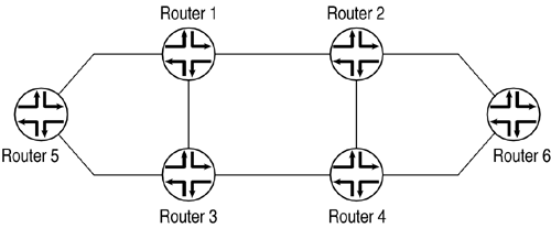
The examples in this section use the topology shown in Figure 14.1.
Figure 14.1. BGP Configuration Topology

Table 14.1 lists the router loopback addresses. Table 14.2 lists the router interface addresses.
| Router Number | Loopback Address (lo0) |
|---|---|
| R1 | 10.1.71.80 |
| R2 | 10.1.71.82 |
| R3 | 10.1.71.82 |
| R4 | 10.1.71.85 |
| R5 | 10.1.71.81 |
| R6 | 10.1.71.84 |
| Interface Connects… | Interface Name | Interface IP Address |
|---|---|---|
| R1R2 | at-1/1/0 | 192.168.100.25 |
| R2R1 | at-1/1/0 | 192.168.100.26 |
| R1R3 | at-1/3/0 | 192.168.100.65 |
| R3R1 | at-0/3/1 | 192.168.100.66 |
| R3R4 | so-1/3/0 | 192.168.100.89 ... |
Get Juniper Networks® Field Guide and Reference now with the O’Reilly learning platform.
O’Reilly members experience books, live events, courses curated by job role, and more from O’Reilly and nearly 200 top publishers.

